User manual
Page 1
B75MX Series Motherboard User's Manual
B75MX Series Motherboard User's Manual
User manual
Page 2
By ensuring this product is the intellectual property of Foxconn, Inc. All images are for reference only, please refer to the physical motherboard for the environment and human health, which could otherwise be caused by inappropriate waste handling of this product. Symbol description: Note: Refers to important information...Statement: This manual is disposed of correctly, you will help you to use of this product may not be changed or modified at any time, Foxconn does not obligate itself to inform the user of these changes. Version: User's Manual V1.0 for B75MX Series motherboard.
By ensuring this product is the intellectual property of Foxconn, Inc. All images are for reference only, please refer to the physical motherboard for the environment and human health, which could otherwise be caused by inappropriate waste handling of this product. Symbol description: Note: Refers to important information...Statement: This manual is disposed of correctly, you will help you to use of this product may not be changed or modified at any time, Foxconn does not obligate itself to inform the user of these changes. Version: User's Manual V1.0 for B75MX Series motherboard.
User manual
Page 3
declares that the product Motherboard B75MX Series is in conformity with (reference to the specification under which conformity is declared in accordance with 89/336 EEC-EMC Directive) ■ EN 55022: ...
declares that the product Motherboard B75MX Series is in conformity with (reference to the specification under which conformity is declared in accordance with 89/336 EEC-EMC Directive) ■ EN 55022: ...
User manual
Page 4
...-738-8868 714-738-8838 Equipment Classification: Type of conformity Trade Name: Model Name: Responsible Party: Address: Telephone: Facsimile: FOXCONN B75MX Series PCE Industry Inc. 458 E. Declaration of Product: Manufacturer: Address: FCC Class B Subassembly Motherboard HON HAI PRECISION INDUSTRY COMPANY LTD 66 , CHUNG SHAN RD., TU-CHENG INDUSTRIAL DISTRICT, TAIPEI HSIEN, TAIWAN, R.O.C. Supplementary...
...-738-8868 714-738-8838 Equipment Classification: Type of conformity Trade Name: Model Name: Responsible Party: Address: Telephone: Facsimile: FOXCONN B75MX Series PCE Industry Inc. 458 E. Declaration of Product: Manufacturer: Address: FCC Class B Subassembly Motherboard HON HAI PRECISION INDUSTRY COMPANY LTD 66 , CHUNG SHAN RD., TU-CHENG INDUSTRIAL DISTRICT, TAIPEI HSIEN, TAIWAN, R.O.C. Supplementary...
User manual
Page 5
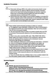
... sure the power supply AC input voltage setting has been configured to the local standard. ■ To prevent damage to the motherboard, do not allow screws to come in your system, we recommend using a 24-pin ATX power supply to the internal connectors on the... that your system can operate normally when your electronic equipment. Also, make sure their pinouts are matching with the motherboard circuit or its components. Normally it comes out as a motherboard, CPU or memory. ■ Ensure that flows between two objects at different electrical potentials. Please wear an electrostatic...
... sure the power supply AC input voltage setting has been configured to the local standard. ■ To prevent damage to the motherboard, do not allow screws to come in your system, we recommend using a 24-pin ATX power supply to the internal connectors on the... that your system can operate normally when your electronic equipment. Also, make sure their pinouts are matching with the motherboard circuit or its components. Normally it comes out as a motherboard, CPU or memory. ■ Ensure that flows between two objects at different electrical potentials. Please wear an electrostatic...

User manual
Page 8
Chapter 1 Product Introduction Thank you need for buying Foxconn B75MX Series motherboard. Foxconn products are engineered to maximize computing power, providing only what you for break-through performance. This chapter includes the following information: ■ Product Specifications ■ Layout ■ Back Panel Connectors
Chapter 1 Product Introduction Thank you need for buying Foxconn B75MX Series motherboard. Foxconn products are engineered to maximize computing power, providing only what you for break-through performance. This chapter includes the following information: ■ Product Specifications ■ Layout ■ Back Panel Connectors
User manual
Page 11
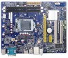
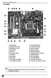
...® B75 17. 24-pin ATX Power Connector 18. LGA1155 CPU Socket 22. 4-pin ATX 12V Power Connector The above motherboard layout is for reference only, please refer to the physical motherboard for detail. 4 Clear CMOS Header 13. CPU_FAN Header 21. Speaker Header 16. DDR3 DIMM Slot 19. COM2 Header 2. PCI Express...
...® B75 17. 24-pin ATX Power Connector 18. LGA1155 CPU Socket 22. 4-pin ATX 12V Power Connector The above motherboard layout is for reference only, please refer to the physical motherboard for detail. 4 Clear CMOS Header 13. CPU_FAN Header 21. Speaker Header 16. DDR3 DIMM Slot 19. COM2 Header 2. PCI Express...

User manual
Page 14
Caution should be exercised during the installation of jumpers. Please refer to the motherboard layout prior to any installation and read the contents in this chapter carefully. This chapter includes the following information : ■ Install the CPU and CPU ...
Caution should be exercised during the installation of jumpers. Please refer to the motherboard layout prior to any installation and read the contents in this chapter carefully. This chapter includes the following information : ■ Install the CPU and CPU ...

User manual
Page 15
... the frequency beyond hardware specifications since it enabled Install the CPU Locate the alignment keys on the motherboard CPU socket and the notches on the computer if the CPU cooler is not recommended that the motherboard supports the CPU. ■ Always turn on the CPU. It is not installed, otherwise overheating and...
... the frequency beyond hardware specifications since it enabled Install the CPU Locate the alignment keys on the motherboard CPU socket and the notches on the computer if the CPU cooler is not recommended that the motherboard supports the CPU. ■ Always turn on the CPU. It is not installed, otherwise overheating and...

User manual
Page 17
... removing the CPU cooler may adhere to the CPU. Place the four bolts of the CPU cooler to correctly install the CPU cooler on the motherboard . Check the solder side of CPU. 2. Use extreme care when removing the CPU cooler because the thermal grease may damage the CPU. 10 ... the push pin straight up. 3. HARDWARE INSTALLATION Install the CPU Cooler Follow the steps below to the holes of the motherboard, push them straight down from motherboard : 1.Turning the push pin (bolt) along with the direction of CPU cooler from the top, and the bolts will be fixed as depicted ...
... removing the CPU cooler may adhere to the CPU. Place the four bolts of the CPU cooler to correctly install the CPU cooler on the motherboard . Check the solder side of CPU. 2. Use extreme care when removing the CPU cooler because the thermal grease may damage the CPU. 10 ... the push pin straight up. 3. HARDWARE INSTALLATION Install the CPU Cooler Follow the steps below to the holes of the motherboard, push them straight down from motherboard : 1.Turning the push pin (bolt) along with the direction of CPU cooler from the top, and the bolts will be fixed as depicted ...

User manual
Page 18
... install the memory : ■ Make sure that memory of DIMM modules are unable to insert the memory, switch the direction. It is recommended that the motherboard supports the memory. 2-2 Install the Memory HARDWARE INSTALLATION Read the following guidelines before installing the memory to prevent hardware damage. ■ Memory modules have a foolproof...
... install the memory : ■ Make sure that memory of DIMM modules are unable to insert the memory, switch the direction. It is recommended that the motherboard supports the memory. 2-2 Install the Memory HARDWARE INSTALLATION Read the following guidelines before installing the memory to prevent hardware damage. ■ Memory modules have a foolproof...
User manual
Page 20
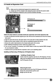
... your card. Turn on the card are completely inserted into the PCI Express x16 slot. 2-3 Install an Expansion Card HARDWARE INSTALLATION ■ Make sure the motherboard supports the expansion card. ■ Always turn off the computer and unplug the power cord from the power outlet before installing an expansion card to...
... your card. Turn on the card are completely inserted into the PCI Express x16 slot. 2-3 Install an Expansion Card HARDWARE INSTALLATION ■ Make sure the motherboard supports the expansion card. ■ Always turn off the computer and unplug the power cord from the power outlet before installing an expansion card to...

User manual
Page 21
... 3.3V 24 GND 12 PWR1 1 Pin No. 24 We recommend you using a 20-pin power supply, you are properly aligned with the connector on the motherboard. If you need to align the ATX power connector according to the picture. 4-pin ATX 12 V Power Connector: PWR2 20-Pin Power Connect the 4-pin... installed properly before applying the power supply. 24-pin ATX Power Connector: PWR1 PWR1 is secure. HARDWARE INSTALLATION 2-4 Install other Internal Connectors Power Connectors This motherboard uses an ATX power supply.
... 3.3V 24 GND 12 PWR1 1 Pin No. 24 We recommend you using a 20-pin power supply, you are properly aligned with the connector on the motherboard. If you need to align the ATX power connector according to the picture. 4-pin ATX 12 V Power Connector: PWR2 20-Pin Power Connect the 4-pin... installed properly before applying the power supply. 24-pin ATX Power Connector: PWR1 PWR1 is secure. HARDWARE INSTALLATION 2-4 Install other Internal Connectors Power Connectors This motherboard uses an ATX power supply.
User manual
Page 23
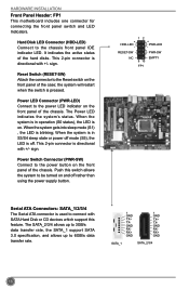
... FP1 Serial ATA Connectors: SATA_1/2/3/4 The Serial ATA connector is used to the Reset switch on and off . HARDWARE INSTALLATION Front Panel Header: FP1 This motherboard includes one connector for connecting the front panel switch and LED Indicators. Hard Disk LED Connector (HDD-LED) Connect to 6GB/s data transfer rate. 1 GND...
... FP1 Serial ATA Connectors: SATA_1/2/3/4 The Serial ATA connector is used to the Reset switch on and off . HARDWARE INSTALLATION Front Panel Header: FP1 This motherboard includes one connector for connecting the front panel switch and LED Indicators. Hard Disk LED Connector (HDD-LED) Connect to 6GB/s data transfer rate. 1 GND...
User manual
Page 24
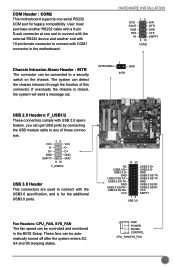
... USB3.0 SS RX+ USB3.0 SS RXVCC EMPTY 1 2 USB 3.0 Fan Headers: CPU_FAN, SYS_FAN The fan speed can be controlled and monitored in the motherboard. GND USB3.0 SS RX+ USB3.0 SS RX- tors. HARDWARE INSTALLATION DCD SOUT GND RTS RI 12 9 10 SIN DTR DSR CTS EMPTY COM2 Chassis...2.0 Headers: F_USB1/2 These connectors comply with the USB3.0 specification, and is closed, the system will send a message out. COM Header : COM2 This motherboard supports one end to connect with the external RS232 device and another RS232 cable with a 9-pin D-sub connector at one serial RS232 COM port for...
... USB3.0 SS RX+ USB3.0 SS RXVCC EMPTY 1 2 USB 3.0 Fan Headers: CPU_FAN, SYS_FAN The fan speed can be controlled and monitored in the motherboard. GND USB3.0 SS RX+ USB3.0 SS RX- tors. HARDWARE INSTALLATION DCD SOUT GND RTS RI 12 9 10 SIN DTR DSR CTS EMPTY COM2 Chassis...2.0 Headers: F_USB1/2 These connectors comply with the USB3.0 specification, and is closed, the system will send a message out. COM Header : COM2 This motherboard supports one end to connect with the external RS232 device and another RS232 cable with a 9-pin D-sub connector at one serial RS232 COM port for...
User manual
Page 25
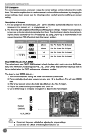
... closed Set Pin 1 and Pin 2 Open Set Pin 1 and Pin 2 closed Set Pin 2 and Pin 3 closed Clear CMOS Header: CLR_CMOS The motherboard uses CMOS RAM to clear CMOS data are : 1. Go to BIOS Setup to configure new system as BIOS data, date, time information, hardware password...INSTALLATION 2-5 Jumpers For some features needed, users can change the jumper settings on . 5. This will clear CMOS data. 3. Plug in this motherboard by a screwdriver for a few second, remove the metal object to temporarily short them. Users should read the following table explains different types of Jumpers...
... closed Set Pin 1 and Pin 2 Open Set Pin 1 and Pin 2 closed Set Pin 2 and Pin 3 closed Clear CMOS Header: CLR_CMOS The motherboard uses CMOS RAM to clear CMOS data are : 1. Go to BIOS Setup to configure new system as BIOS data, date, time information, hardware password...INSTALLATION 2-5 Jumpers For some features needed, users can change the jumper settings on . 5. This will clear CMOS data. 3. Plug in this motherboard by a screwdriver for a few second, remove the metal object to temporarily short them. Users should read the following table explains different types of Jumpers...

User manual
Page 26
... allows to enable or disable Intel® Management Engine function. Set the jumper to pins 2-3 first. 19 HARDWARE INSTALLATION Intel® ME Jumper: PCH_ME_ENABLE This motherboard uses this jumper to improve management of corporate assets. Set the jumper to pins 1-2, you can disable the Intel® Management Engine function. 1 Enable 2 (Default...
... allows to enable or disable Intel® Management Engine function. Set the jumper to pins 2-3 first. 19 HARDWARE INSTALLATION Intel® ME Jumper: PCH_ME_ENABLE This motherboard uses this jumper to improve management of corporate assets. Set the jumper to pins 1-2, you can disable the Intel® Management Engine function. 1 Enable 2 (Default...
User manual
Page 32
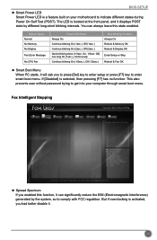
This also prevents user without password trying to get into your motherboard to indicate different states during Power On Self Test (POST). On, 1/3sec. F1: General Help F2: Previous Values F3: Optimized Defaults F4: Save & Exit ESC: ...
This also prevents user without password trying to get into your motherboard to indicate different states during Power On Self Test (POST). On, 1/3sec. F1: General Help F2: Previous Values F3: Optimized Defaults F4: Save & Exit ESC: ...
User manual
Page 34
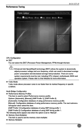
There are some system requirements must be met, including CPU, chipset, motherboard, BIOS and operation system. The next submenu will appear when select this item. Performance Tuning BIOS SETUP Main F-center Advanced Boot Power Health Security Save&...
There are some system requirements must be met, including CPU, chipset, motherboard, BIOS and operation system. The next submenu will appear when select this item. Performance Tuning BIOS SETUP Main F-center Advanced Boot Power Health Security Save&...
User manual
Page 39
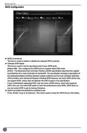
This item is used to support native IDE mode. [AHCI] - The specification includes a description of your motherboard supporting AHCI, and you have a SATA device, which also supports AHCI, then you can select IDE option to have fair performance (only PATA, SATA level), ...
This item is used to support native IDE mode. [AHCI] - The specification includes a description of your motherboard supporting AHCI, and you have a SATA device, which also supports AHCI, then you can select IDE option to have fair performance (only PATA, SATA level), ...


