User manual
Page 5
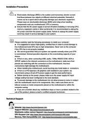
....aspx CPU Support List: http://www.foxconnsupport.com/cpusupportlist.aspx Memory, VGA Compatibility List: http://www.foxconnsupport.com/complist.aspx Normal operation depends on the overclocking capacity of the product, please consult a certified computer technician. Incorrect connections might damage the motherboard. ■ When handling the motherboard, avoid touching any , when connecting USB, audio, 1394a, RS232 COM, IrDA or S/PDIF cables to the internal connectors on the motherboard, make...
....aspx CPU Support List: http://www.foxconnsupport.com/cpusupportlist.aspx Memory, VGA Compatibility List: http://www.foxconnsupport.com/complist.aspx Normal operation depends on the overclocking capacity of the product, please consult a certified computer technician. Incorrect connections might damage the motherboard. ■ When handling the motherboard, avoid touching any , when connecting USB, audio, 1394a, RS232 COM, IrDA or S/PDIF cables to the internal connectors on the motherboard, make...
User manual
Page 6
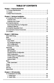
... Specifications 2 1-2 Layout...4 1-3 Back Panel Connectors 5 Chapter 2 Hardware Installation 2-1 Install the CPU and CPU Cooler 8 Install the CPU 8 Install the CPU Cooler 10 2-2 Install the Memory 11 Dual Channel Memory Configuration 11 Installing a Memory 12 2-3 Install an Expansion Card 13 2-4 Install other Internal Connectors 14 2-5 Jumpers 18 Chapter 3 BIOS Setup Enter BIOS Setup 21 Main...22 F-center...24 Smart BIOS 24 Fox Intelligent Stepping 25 CPU Configuration 26 Performance Tuning 27 Advanced...29 North Bridge 29 ME Subsystem 30 Onboard Device Configuration 31 SATA...
... Specifications 2 1-2 Layout...4 1-3 Back Panel Connectors 5 Chapter 2 Hardware Installation 2-1 Install the CPU and CPU Cooler 8 Install the CPU 8 Install the CPU Cooler 10 2-2 Install the Memory 11 Dual Channel Memory Configuration 11 Installing a Memory 12 2-3 Install an Expansion Card 13 2-4 Install other Internal Connectors 14 2-5 Jumpers 18 Chapter 3 BIOS Setup Enter BIOS Setup 21 Main...22 F-center...24 Smart BIOS 24 Fox Intelligent Stepping 25 CPU Configuration 26 Performance Tuning 27 Advanced...29 North Bridge 29 ME Subsystem 30 Onboard Device Configuration 31 SATA...
User manual
Page 9
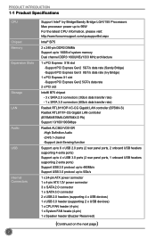
... 1-1 Product Specifications CPU Chipset Memory Expansion Slots Storage LAN Audio USB Internal Connectors Support Intel® Ivy Bridge/Sandy Bridge LGA1155 Processors Max processor power up to 95W For the latest CPU information, please visit: http://www.foxconnsupport.com/cpusupportlist.aspx Intel® B75 2 x 240-pin DDR3 DIMMs Support up to 16GB of system memory Dual channel DDR3 1600(IVB)/1333 MHz architecture 1 x PCI Express X16 slot -Support PCI Express Gen2 5GT/s data rate (Sandy Bridge) -Support PCI Express Gen3 8GT...
... 1-1 Product Specifications CPU Chipset Memory Expansion Slots Storage LAN Audio USB Internal Connectors Support Intel® Ivy Bridge/Sandy Bridge LGA1155 Processors Max processor power up to 95W For the latest CPU information, please visit: http://www.foxconnsupport.com/cpusupportlist.aspx Intel® B75 2 x 240-pin DDR3 DIMMs Support up to 16GB of system memory Dual channel DDR3 1600(IVB)/1333 MHz architecture 1 x PCI Express X16 slot -Support PCI Express Gen2 5GT/s data rate (Sandy Bridge) -Support PCI Express Gen3 8GT...

User manual
Page 14
... chapter introduces the hardware installation process, including the installation of the CPU, memory, power supply, slots, pin headers and the mounting of these modules. Caution should be exercised during the installation of jumpers. This chapter includes the following information : ■ Install the CPU and CPU Cooler ■ Install the Memory ■ Install an Expansion Card ■ Install other Internal Connectors ■ Jumpers Please refer to the motherboard layout prior to any installation and read the...
... chapter introduces the hardware installation process, including the installation of the CPU, memory, power supply, slots, pin headers and the mounting of these modules. Caution should be exercised during the installation of jumpers. This chapter includes the following information : ■ Install the CPU and CPU Cooler ■ Install the Memory ■ Install an Expansion Card ■ Install other Internal Connectors ■ Jumpers Please refer to the motherboard layout prior to any installation and read the...
User manual
Page 20
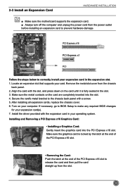
... the motherboard supports the expansion card. ■ Always turn off the computer and unplug the power cord from the power outlet before installing an expansion card to the chassis back panel with a screw. 5. Locate an expansion slot that supports your expansion card in the expansion slot. 1. Secure the card's metal bracket to prevent hardware damage. Installing and Removing a PCI Express x16 Graphics Card: • Installing a Graphics Card: Gently insert the graphics card into the slot. 4. Make sure the graphics card...
... the motherboard supports the expansion card. ■ Always turn off the computer and unplug the power cord from the power outlet before installing an expansion card to the chassis back panel with a screw. 5. Locate an expansion slot that supports your expansion card in the expansion slot. 1. Secure the card's metal bracket to prevent hardware damage. Installing and Removing a PCI Express x16 Graphics Card: • Installing a Graphics Card: Gently insert the graphics card into the slot. 4. Make sure the graphics card...
User manual
Page 23
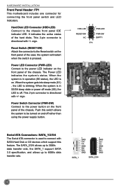
... restart when the switch is directional with SATA Hard Disk or CD devices which support this switch allows the system to the power button on the front panel of the chassis. The SATA_2/3/4 allows up to 3GB/s data transfer rate, the SATA_1 support SATA 3.0 specification, and allows up to the chassis front panel IDE indicator LED. sign. Power LED Connector (PWR-LED) Connect to the Reset switch on the front panel of the case; Hard Disk LED Connector (HDD-LED) Connect to 6GB/s data...
... restart when the switch is directional with SATA Hard Disk or CD devices which support this switch allows the system to the power button on the front panel of the chassis. The SATA_2/3/4 allows up to 3GB/s data transfer rate, the SATA_1 support SATA 3.0 specification, and allows up to the chassis front panel IDE indicator LED. sign. Power LED Connector (PWR-LED) Connect to the Reset switch on the front panel of the case; Hard Disk LED Connector (HDD-LED) Connect to 6GB/s data...
User manual
Page 25
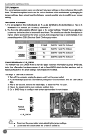
... jumper on the two pins to modify them. Jumper 1 1 Diagram 1 1 1 1 Definition Closed Open 1-2 2-3 Description Set Pin 1 and Pin 2 closed Set Pin 1 and Pin 2 Open Set Pin 1 and Pin 2 closed Set Pin 2 and Pin 3 closed Clear CMOS Header: CLR_CMOS The motherboard uses CMOS RAM to factory default when the BIOS settings were mistakenly modified. The following content carefully prior to it on. 5. This will clear CMOS data. 3. Clear CMOS data is turned on. 18 Go to BIOS Setup to use the various functions of this motherboard...
... jumper on the two pins to modify them. Jumper 1 1 Diagram 1 1 1 1 Definition Closed Open 1-2 2-3 Description Set Pin 1 and Pin 2 closed Set Pin 1 and Pin 2 Open Set Pin 1 and Pin 2 closed Set Pin 2 and Pin 3 closed Clear CMOS Header: CLR_CMOS The motherboard uses CMOS RAM to factory default when the BIOS settings were mistakenly modified. The following content carefully prior to it on. 5. This will clear CMOS data. 3. Clear CMOS data is turned on. 18 Go to BIOS Setup to use the various functions of this motherboard...

User manual
Page 26
... 1-2(default) 2-3 Description Set Pin 1 and Pin 2 closed Set Pin 2 and Pin 3 closed Function Enable ME function Disable ME function CAUTION Before flashing BIOS ROM, you need to set ME jumper to pins 2-3, you can enable the Intel® Management Engine function. HARDWARE INSTALLATION Intel® ME Jumper: PCH_ME_ENABLE This motherboard uses this jumper to improve management of corporate assets. Intel® Management Engine (ME) is an embedded microcontroller located in Intel chipset. It...
... 1-2(default) 2-3 Description Set Pin 1 and Pin 2 closed Set Pin 2 and Pin 3 closed Function Enable ME function Disable ME function CAUTION Before flashing BIOS ROM, you need to set ME jumper to pins 2-3, you can enable the Intel® Management Engine function. HARDWARE INSTALLATION Intel® ME Jumper: PCH_ME_ENABLE This motherboard uses this jumper to improve management of corporate assets. Intel® Management Engine (ME) is an embedded microcontroller located in Intel chipset. It...
User manual
Page 28
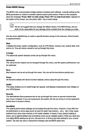
... The Administrator/User password can be set up through this menu. Use the arrow right/left keys to select a specific function and go to enter Setup. They all can be viewed or set up the BIOS parameters is critical to find out the best setting for the chipset can be changed through this menu. Boot Boot features can press key to the submenu. If you have more memory or I/O cards installed.
... The Administrator/User password can be set up through this menu. Use the arrow right/left keys to select a specific function and go to enter Setup. They all can be viewed or set up the BIOS parameters is critical to find out the best setting for the chipset can be changed through this menu. Boot Boot features can press key to the submenu. If you have more memory or I/O cards installed.
User manual
Page 31
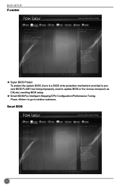
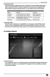
...: Exit Version 2.15.1234. Smart BIOS Main F-center Advanced Boot Smart BIOS Power Health Smart Power LED Smart Boot Menu [Disabled] [Enabled] Security Save&Exit Smart Power LED Settings 24 → ←: Select Screen ↑ ↓: Select Item Enter: Select +/-: Change Opt. Copyright (C) 2012 American Megatrends, Inc. Copyright (C) 2012 American Megatrends, Inc. ► Super BIOS Protect To protect the system BIOS, there is a BIOS write-protection mechanism provided to prevent BIOS FLASH tool being improperly used to update BIOS or the...
...: Exit Version 2.15.1234. Smart BIOS Main F-center Advanced Boot Smart BIOS Power Health Smart Power LED Smart Boot Menu [Disabled] [Enabled] Security Save&Exit Smart Power LED Settings 24 → ←: Select Screen ↑ ↓: Select Item Enter: Select +/-: Change Opt. Copyright (C) 2012 American Megatrends, Inc. Copyright (C) 2012 American Megatrends, Inc. ► Super BIOS Protect To protect the system BIOS, there is a BIOS write-protection mechanism provided to prevent BIOS FLASH tool being improperly used to update BIOS or the...
User manual
Page 32
... & Fan OK ► Smart Boot Menu When PC starts, it . 25 This also prevents user without password trying to comply with FCC regulation. You can significantly reduce the EMI (Electromagnetic Interference) generated by different long-short blinking intervals. F1: General Help F2: Previous Values F3: Optimized Defaults F4: Save & Exit ESC: Exit Version 2.15.1234. But if overclocking is located at the front panel...
... & Fan OK ► Smart Boot Menu When PC starts, it . 25 This also prevents user without password trying to comply with FCC regulation. You can significantly reduce the EMI (Electromagnetic Interference) generated by different long-short blinking intervals. F1: General Help F2: Previous Values F3: Optimized Defaults F4: Save & Exit ESC: Exit Version 2.15.1234. But if overclocking is located at the front panel...
User manual
Page 33
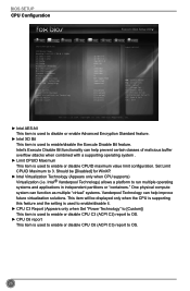
... used to disable or enable Advanced Encryption Standard feature. ► Intel XD Bit This item is used to enable/disable the Execute Disable Bit feature. BIOS SETUP CPU Configuration Main F-center Advanced Boot CPU Configuration CPU Brand Name: Genuine Intel(R) CPU @ 2.20GHz L1 Data Cache L1 Code Cache L2 Cache L3 Cache Processor Stepping Max CPU Speed Min CPU Speed Current CPU Speed Processor Cores Intel HT Technology Intel VT-x Technology Intel SMX Technology Intel AES-NI Intel XD Bit Limit CPUID Maximum Intel Virtualization Technology CPU...
... used to disable or enable Advanced Encryption Standard feature. ► Intel XD Bit This item is used to enable/disable the Execute Disable Bit feature. BIOS SETUP CPU Configuration Main F-center Advanced Boot CPU Configuration CPU Brand Name: Genuine Intel(R) CPU @ 2.20GHz L1 Data Cache L1 Code Cache L2 Cache L3 Cache Processor Stepping Max CPU Speed Min CPU Speed Current CPU Speed Processor Cores Intel HT Technology Intel VT-x Technology Intel SMX Technology Intel AES-NI Intel XD Bit Limit CPUID Maximum Intel Virtualization Technology CPU...
User manual
Page 34
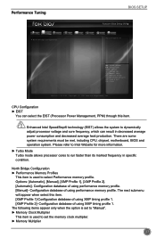
... must be met, including CPU, chipset, motherboard, BIOS and operation system. F1: General Help F2: Previous Values F3: Optimized Defaults F4: Save & Exit ESC: Exit Version 2.15.1234. Enhanced Intel SpeedStep® technology (EIST) allows the system to set to "Manual". ► Memory Clock Multiplier This item is used to dynamically adjust processor voltage and core frequency, which can select the EIST (Processor Power Management, PPM) through this...
... must be met, including CPU, chipset, motherboard, BIOS and operation system. F1: General Help F2: Previous Values F3: Optimized Defaults F4: Save & Exit ESC: Exit Version 2.15.1234. Enhanced Intel SpeedStep® technology (EIST) allows the system to set to "Manual". ► Memory Clock Multiplier This item is used to dynamically adjust processor voltage and core frequency, which can select the EIST (Processor Power Management, PPM) through this...
User manual
Page 37
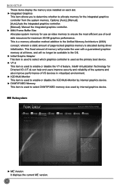
... Subsystem Main F-center Advanced Boot Intel ME Subsystem Configuration ME Version Power Health 8.1.20.1336 Security Save&Exit → ←: Select Screen ↑ ↓: Select Item Enter: Select +/-: Change Opt. Copyright (C) 2012 American Megatrends, Inc. ► ME Version It displays the current ME version. 30 Manual the integrated graphics controller. ► UMA Frame Buffer Size Allocates system memory for use of I /O (VT-d) can help end users improve security...
... Subsystem Main F-center Advanced Boot Intel ME Subsystem Configuration ME Version Power Health 8.1.20.1336 Security Save&Exit → ←: Select Screen ↑ ↓: Select Item Enter: Select +/-: Change Opt. Copyright (C) 2012 American Megatrends, Inc. ► ME Version It displays the current ME version. 30 Manual the integrated graphics controller. ► UMA Frame Buffer Size Allocates system memory for use of I /O (VT-d) can help end users improve security...
User manual
Page 38
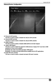
...Configuration BIOS SETUP Main F-center Advanced Boot Power Health Security Save&Exit Onboard Device Configuration Onboard LAN Controller Onboard USB Controller USB3.0 Support Legacy USB Support Azalia HD Audio controller [Enabled] [Enabled] [Enabled] [Enabled] [Enabled] Onboard LAN Controller → ←: Select Screen ↑ ↓: Select Item Enter: Select +/-: Change Opt. Copyright (C) 2012 American Megatrends, Inc. ► Onboard LAN Controller This item is used to enable or disable the onboard LAN controller ► Onboard USB Controller This item is used to enable...
...Configuration BIOS SETUP Main F-center Advanced Boot Power Health Security Save&Exit Onboard Device Configuration Onboard LAN Controller Onboard USB Controller USB3.0 Support Legacy USB Support Azalia HD Audio controller [Enabled] [Enabled] [Enabled] [Enabled] [Enabled] Onboard LAN Controller → ←: Select Screen ↑ ↓: Select Item Enter: Select +/-: Change Opt. Copyright (C) 2012 American Megatrends, Inc. ► Onboard LAN Controller This item is used to enable or disable the onboard LAN controller ► Onboard USB Controller This item is used to enable...
User manual
Page 39
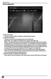
... Values F3: Optimized Defaults F4: Save & Exit ESC: Exit Version 2.15.1234. If your SATA ports. [Native IDE] - The specification includes a description of your motherboard supporting AHCI, and you have a SATA device, which also supports AHCI, then you can select IDE option to have fair performance (only PATA, SATA level), or you can select AHCI to get its specification. BIOS SETUP SATA Configuration Main F-center Advanced Boot Power Health Security Save&Exit SATA Configuration SATA Controller(s) Onboard SATA Mode ▶ SATA Port1: Not...
... Values F3: Optimized Defaults F4: Save & Exit ESC: Exit Version 2.15.1234. If your SATA ports. [Native IDE] - The specification includes a description of your motherboard supporting AHCI, and you have a SATA device, which also supports AHCI, then you can select IDE option to have fair performance (only PATA, SATA level), or you can select AHCI to get its specification. BIOS SETUP SATA Configuration Main F-center Advanced Boot Power Health Security Save&Exit SATA Configuration SATA Controller(s) Onboard SATA Mode ▶ SATA Port1: Not...
User manual
Page 41
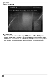
... to support TPM, first you need to install a TPM device on the motherboard and set this item to support TPM (Trusted Platform Module) device function. BIOS SETUP Trusted Computing Main F-center Advanced Boot TPM Configuration TPM SUPPORT Current TPM Status Information NO TPM Hardware Power Health [Disabled] Security Save&Exit Enables or Disables BIOS support O.S. F1: General Help F2: Previous Values F3: Optimized Defaults F4: Save & Exit ESC: Exit Version 2.15...
... to support TPM, first you need to install a TPM device on the motherboard and set this item to support TPM (Trusted Platform Module) device function. BIOS SETUP Trusted Computing Main F-center Advanced Boot TPM Configuration TPM SUPPORT Current TPM Status Information NO TPM Hardware Power Health [Disabled] Security Save&Exit Enables or Disables BIOS support O.S. F1: General Help F2: Previous Values F3: Optimized Defaults F4: Save & Exit ESC: Exit Version 2.15...

User manual
Page 43
...; USB KEY Drive BBS Priorities ▶ UEFI Boot Drive BBS Prioriies Power Health [On] [Enabled] [Disabled] [Enabled] [Hard Disk] [CD/DVD] [USB Floppy] [USB CD/DVD] [USB Hard Disk] [USB KEY] [Network] [UEFI] Security Save&Exit Select the keyboard NumLock state → ←: Select Screen ↑ ↓: Select Item Enter: Select +/-: Change Opt. The available settings are available. This is started. F1: General Help F2: Previous Values F3: Optimized Defaults F4: Save & Exit ESC: Exit Version 2.15.1234. Use this item can allow Option ROMs...
...; USB KEY Drive BBS Priorities ▶ UEFI Boot Drive BBS Prioriies Power Health [On] [Enabled] [Disabled] [Enabled] [Hard Disk] [CD/DVD] [USB Floppy] [USB CD/DVD] [USB Hard Disk] [USB KEY] [Network] [UEFI] Security Save&Exit Select the keyboard NumLock state → ←: Select Screen ↑ ↓: Select Item Enter: Select +/-: Change Opt. The available settings are available. This is started. F1: General Help F2: Previous Values F3: Optimized Defaults F4: Save & Exit ESC: Exit Version 2.15.1234. Use this item can allow Option ROMs...
User manual
Page 47
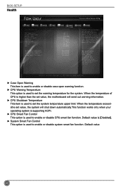
...: Optimized Defaults F4: Save & Exit ESC: Exit Version 2.15.1234. BIOS SETUP Health Main F-center Advanced Boot Power Health Security Save&Exit Case Open Warning CPU Temperature System Temperature CPU Fan Speed System Fan Speed CPU Vcore DRAM Voltage +12V SYS +5V SYS VBAT [Disabled] : +39 ˚C : +35 ˚C : 3026 RPM : N/A : +1.200 V : +1.608 V : +21.300 V : +5.097 V : +3.328 V Enabled Case Opening Warning and open warning function. ► CPU Warning Temperature This option is used to enable or disable CPU smart fan function...
...: Optimized Defaults F4: Save & Exit ESC: Exit Version 2.15.1234. BIOS SETUP Health Main F-center Advanced Boot Power Health Security Save&Exit Case Open Warning CPU Temperature System Temperature CPU Fan Speed System Fan Speed CPU Vcore DRAM Voltage +12V SYS +5V SYS VBAT [Disabled] : +39 ˚C : +35 ˚C : 3026 RPM : N/A : +1.200 V : +1.608 V : +21.300 V : +5.097 V : +3.328 V Enabled Case Opening Warning and open warning function. ► CPU Warning Temperature This option is used to enable or disable CPU smart fan function...
User manual
Page 51
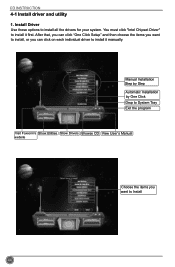
Install Driver Use these options to install it manually. Manual Installation Step by Step Automatic Installation by One Click Drop to System Tray Exit the program Visit Foxconn's Show Utilities Show Drivers Browse CD View User's Manual website Choose the items you want to install, or you want to install it first. After that, you can click "One Click Setup" and then choose the items you can click on each individual driver to Install 44 CD INSTRUCTION 4-1 Install driver and utility 1. You must click "Intel Chipset Driver" to install all the drivers for your system.
Install Driver Use these options to install it manually. Manual Installation Step by Step Automatic Installation by One Click Drop to System Tray Exit the program Visit Foxconn's Show Utilities Show Drivers Browse CD View User's Manual website Choose the items you want to install, or you want to install it first. After that, you can click "One Click Setup" and then choose the items you can click on each individual driver to Install 44 CD INSTRUCTION 4-1 Install driver and utility 1. You must click "Intel Chipset Driver" to install all the drivers for your system.


