User manual
Page 6
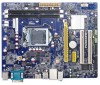
... Channel Memory Configuration 11 Installing a Memory 12 2-3 Install an Expansion Card 13 2-4 Install other Internal Connectors 14 2-5 Jumpers 18 Chapter 3 BIOS Setup Enter BIOS Setup 21 Main...22 F-center...24 Smart BIOS 24 Fox Intelligent Stepping 25 CPU Configuration 26 Performance Tuning 27 Advanced...29 North Bridge 29 ME Subsystem 30 Onboard Device...
... Channel Memory Configuration 11 Installing a Memory 12 2-3 Install an Expansion Card 13 2-4 Install other Internal Connectors 14 2-5 Jumpers 18 Chapter 3 BIOS Setup Enter BIOS Setup 21 Main...22 F-center...24 Smart BIOS 24 Fox Intelligent Stepping 25 CPU Configuration 26 Performance Tuning 27 Advanced...29 North Bridge 29 ME Subsystem 30 Onboard Device...

User manual
Page 15
...: (Go to install the CPU : ■ Make sure that supports HT Technology and has it does not meet the standard requirements for HT Technology ■ A BIOS that the motherboard supports the CPU. ■ Always turn on the CPU. The CPU cannot be set the frequency beyond hardware specifications since it enabled...
...: (Go to install the CPU : ■ Make sure that supports HT Technology and has it does not meet the standard requirements for HT Technology ■ A BIOS that the motherboard supports the CPU. ■ Always turn on the CPU. The CPU cannot be set the frequency beyond hardware specifications since it enabled...
User manual
Page 20
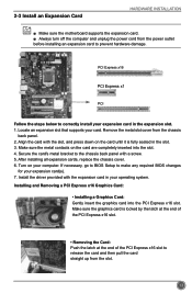
... completely inserted into the PCI Express x16 slot. PCI Express x16 PCI Express x1 PCI Follow the steps below to make any required BIOS changes for your operating system. After installing all expansion cards, replace the chassis cover. 6. Install the driver provided with the expansion...in your expansion card(s). 7. Remove the metal slot cover from the slot. 13 Align the card with a screw. 5. If necessary, go to BIOS Setup to correctly install your card. 2-3 Install an Expansion Card HARDWARE INSTALLATION ■ Make sure the motherboard supports the expansion card. ■ ...
... completely inserted into the PCI Express x16 slot. PCI Express x16 PCI Express x1 PCI Follow the steps below to make any required BIOS changes for your operating system. After installing all expansion cards, replace the chassis cover. 6. Install the driver provided with the expansion...in your expansion card(s). 7. Remove the metal slot cover from the slot. 13 Align the card with a screw. 5. If necessary, go to BIOS Setup to correctly install your card. 2-3 Install an Expansion Card HARDWARE INSTALLATION ■ Make sure the motherboard supports the expansion card. ■ ...
User manual
Page 24
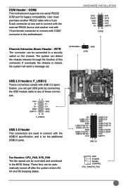
... chassis intrusion through the function of these connec- User must purchase another end with 10-pin female connector to connect with COM1 connector in the BIOS Setup. tors. The system can be connected to a security switch on the chassis. HARDWARE INSTALLATION DCD SOUT GND RTS RI 12 9 10 SIN DTR DSR...
... chassis intrusion through the function of these connec- User must purchase another end with 10-pin female connector to connect with COM1 connector in the BIOS Setup. tors. The system can be connected to a security switch on the chassis. HARDWARE INSTALLATION DCD SOUT GND RTS RI 12 9 10 SIN DTR DSR...
User manual
Page 25
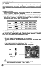
..., remove the metal object to your computer and turn it . Turn off the computer, unplug the power cord from the power outlet. 2. Go to BIOS Setup to configure new system as described in next chapter. 1 Clear 2 3 Normal 1 2 (Default) 3 CLR_CMOS CAUTION ■ Disconnect the power ... go back to modifying any jumper on . 5. Description of the jumper settings. The following content carefully prior to factory default when the BIOS settings were mistakenly modified. After a few seconds, but using jumper cap is recommended. The steps to short them . Users should read ...
..., remove the metal object to your computer and turn it . Turn off the computer, unplug the power cord from the power outlet. 2. Go to BIOS Setup to configure new system as described in next chapter. 1 Clear 2 3 Normal 1 2 (Default) 3 CLR_CMOS CAUTION ■ Disconnect the power ... go back to modifying any jumper on . 5. Description of the jumper settings. The following content carefully prior to factory default when the BIOS settings were mistakenly modified. After a few seconds, but using jumper cap is recommended. The steps to short them . Users should read ...

User manual
Page 26
...) 3 1 Disable 2 3 PCH_ME_ENABLE Definition 1-2(default) 2-3 Description Set Pin 1 and Pin 2 closed Set Pin 2 and Pin 3 closed Function Enable ME function Disable ME function CAUTION Before flashing BIOS ROM, you can enable the Intel® Management Engine function. HARDWARE INSTALLATION Intel® ME Jumper: PCH_ME_ENABLE This motherboard uses this jumper to pins 2-3 first...
...) 3 1 Disable 2 3 PCH_ME_ENABLE Definition 1-2(default) 2-3 Description Set Pin 1 and Pin 2 closed Set Pin 2 and Pin 3 closed Function Enable ME function Disable ME function CAUTION Before flashing BIOS ROM, you can enable the Intel® Management Engine function. HARDWARE INSTALLATION Intel® ME Jumper: PCH_ME_ENABLE This motherboard uses this jumper to pins 2-3 first...
User manual
Page 27
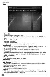
You want to change system settings through the BIOS Setup menus. This chapter includes the following cases occur: 1. An error message appears on the screen during the system Power On Self Test (POST) process. 2. You have to run the Setup Program when the following information : ■ Enter BIOS Setup ■ Main ■ F-Center ■ Advanced ■ Boot ■ Power ■ Health ■ Security ■ Save & Exit Detailed descriptions of the BIOS parameters are also provided. Chapter 3 BIOS Setup This chapter tells how to change the default CMOS settings.
You want to change system settings through the BIOS Setup menus. This chapter includes the following cases occur: 1. An error message appears on the screen during the system Power On Self Test (POST) process. 2. You have to run the Setup Program when the following information : ■ Enter BIOS Setup ■ Main ■ F-Center ■ Advanced ■ Boot ■ Power ■ Health ■ Security ■ Save & Exit Detailed descriptions of the BIOS parameters are also provided. Chapter 3 BIOS Setup This chapter tells how to change the default CMOS settings.
User manual
Page 28
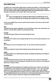
... your CPU/System. Advanced The values for the chipset can be viewed or set a password, the system will ask you to key in the BIOS Setup, and we shall not be changed through this menu. Power All the items related with Green function features can be setup through this menu...read/change the default values in correct password before boot or access to Setup. Enter BIOS Setup BIOS SETUP The BIOS is the communication bridge between hardware and software, correctly setting up the BIOS parameters is to adjust BIOS setting one by one, trial and error, to find out the best setting for your...
... your CPU/System. Advanced The values for the chipset can be viewed or set a password, the system will ask you to key in the BIOS Setup, and we shall not be changed through this menu. Power All the items related with Green function features can be setup through this menu...read/change the default values in correct password before boot or access to Setup. Enter BIOS Setup BIOS SETUP The BIOS is the communication bridge between hardware and software, correctly setting up the BIOS parameters is to adjust BIOS setting one by one, trial and error, to find out the best setting for your...
User manual
Page 29
... Save&Exit System Date System Time Access Level Model Name ME Version BIOS Version Build Date and Time Halt On CPU Brand Name: Genuine Intel(R) CPU @ 2.20GHz Total Memory MAC Address [Tue 12/20/2012] [10:43:34] Administrator B75MX 8.1.20.1336 CA8F1D03 12/15/2012 20:34:16 [All, but keyboard...] Set the Date. If no password is detected during [All Errors]: All errors can check this item will stop if an error is set up by BIOS (Read Only). If you enter system...
... Save&Exit System Date System Time Access Level Model Name ME Version BIOS Version Build Date and Time Halt On CPU Brand Name: Genuine Intel(R) CPU @ 2.20GHz Total Memory MAC Address [Tue 12/20/2012] [10:43:34] Administrator B75MX 8.1.20.1336 CA8F1D03 12/15/2012 20:34:16 [All, but keyboard...] Set the Date. If no password is detected during [All Errors]: All errors can check this item will stop if an error is set up by BIOS (Read Only). If you enter system...

User manual
Page 30
The size is depending on . ► MAC Address This item displays the onboard LAN MAC address. 23 BIOS SETUP [No Errors]: No error can result in system halt. [All, but keyboard]: All errors but keyboard can result in your system before powering on how many memory modules are installed in system halt. ► CPU Brand Name It displays the current CPU name. ► Total Memory This item displays the total memory size.
The size is depending on . ► MAC Address This item displays the onboard LAN MAC address. 23 BIOS SETUP [No Errors]: No error can result in system halt. [All, but keyboard]: All errors but keyboard can result in your system before powering on how many memory modules are installed in system halt. ► CPU Brand Name It displays the current CPU name. ► Total Memory This item displays the total memory size.
User manual
Page 31
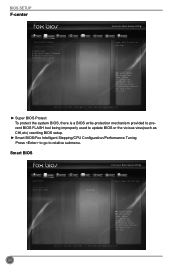
... Help F2: Previous Values F3: Optimized Defaults F4: Save & Exit ESC: Exit Version 2.15.1234. Copyright (C) 2012 American Megatrends, Inc. BIOS SETUP F-center Main F-center Advanced Boot Fox Control Center Super BIOS Protect ▶ Smart BIOS ▶ Fox Intelligent Stepping ▶ CPU Configuration ▶ Performance Tuning Power Health [Enabled] Security Save&Exit Super...
... Help F2: Previous Values F3: Optimized Defaults F4: Save & Exit ESC: Exit Version 2.15.1234. Copyright (C) 2012 American Megatrends, Inc. BIOS SETUP F-center Main F-center Advanced Boot Fox Control Center Super BIOS Protect ▶ Smart BIOS ▶ Fox Intelligent Stepping ▶ CPU Configuration ▶ Performance Tuning Power Health [Enabled] Security Save&Exit Super...
User manual
Page 32
BIOS SETUP ► Smart Power LED Smart Power LED is a feature built on your motherboard to get into your computer through smart boot menu. If [Disabled] ...
BIOS SETUP ► Smart Power LED Smart Power LED is a feature built on your motherboard to get into your computer through smart boot menu. If [Disabled] ...
User manual
Page 33
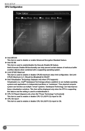
... item is used to enable or disable CPU C3 (ACPI C2) report to OS. ► CPU C6 report This item is used to OS. 26 BIOS SETUP CPU Configuration Main F-center Advanced Boot CPU Configuration CPU Brand Name: Genuine Intel(R) CPU @ 2.20GHz L1 Data Cache L1 Code Cache L2 Cache L3...
... item is used to enable or disable CPU C3 (ACPI C2) report to OS. ► CPU C6 report This item is used to OS. 26 BIOS SETUP CPU Configuration Main F-center Advanced Boot CPU Configuration CPU Brand Name: Genuine Intel(R) CPU @ 2.20GHz L1 Data Cache L1 Code Cache L2 Cache L3...
User manual
Page 34
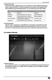
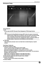
...allows processor cores to set the memory clock multiplier. ► Memory Multiplier 27 Configuration database of using performance memory profile. Performance Tuning BIOS SETUP Main F-center Advanced Boot Power Health Security Save&Exit ▶ CPU Configuration ▶ North Bridge Configuration CPU Configuration CAUTION &#... when select this item. There are some system requirements must be met, including CPU, chipset, motherboard, BIOS and operation system. F1: General Help F2: Previous Values F3: Optimized Defaults F4: Save & Exit ESC: Exit Version 2.15.1234...
...allows processor cores to set the memory clock multiplier. ► Memory Multiplier 27 Configuration database of using performance memory profile. Performance Tuning BIOS SETUP Main F-center Advanced Boot Power Health Security Save&Exit ▶ CPU Configuration ▶ North Bridge Configuration CPU Configuration CAUTION &#... when select this item. There are some system requirements must be met, including CPU, chipset, motherboard, BIOS and operation system. F1: General Help F2: Previous Values F3: Optimized Defaults F4: Save & Exit ESC: Exit Version 2.15.1234...
User manual
Page 35
... a write operation to the memory and issuing a read CAS_L isasserted depends on the memory clock frequency. The value that BIOS programs into the memory controller is a function of the target clock frequency. BIOS SETUP This item is used to return data after the read command. ► tRRD This item allows you to...
... a write operation to the memory and issuing a read CAS_L isasserted depends on the memory clock frequency. The value that BIOS programs into the memory controller is a function of the target clock frequency. BIOS SETUP This item is used to return data after the read command. ► tRRD This item allows you to...

User manual
Page 36
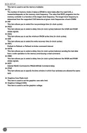
... using memory information. ► Memory Slot 1/2 29 F1: General Help F2: Previous Values F3: Optimized Defaults F4: Save & Exit ESC: Exit Version 2.15.1234. Advanced BIOS SETUP Main F-center Advanced Boot ▶ North Bridge ▶ ME Subsystem ▶ Onboard Device Configuration ▶ SATA Configuration ▶ IT8732 Super IO Configuration ▶ Trusted...
... using memory information. ► Memory Slot 1/2 29 F1: General Help F2: Previous Values F3: Optimized Defaults F4: Save & Exit ESC: Exit Version 2.15.1234. Advanced BIOS SETUP Main F-center Advanced Boot ▶ North Bridge ▶ ME Subsystem ▶ Onboard Device Configuration ▶ SATA Configuration ▶ IT8732 Super IO Configuration ▶ Trusted...
User manual
Page 37
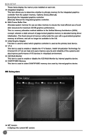
.../FIXED Memory This item is used by internal graphics device. Copyright (C) 2012 American Megatrends, Inc. ► ME Version It displays the current ME version. 30 BIOS SETUP These items display the memory size installed on each slot. ► Integrated Graphics This item allows you to determine whether to allocate memory for...
.../FIXED Memory This item is used by internal graphics device. Copyright (C) 2012 American Megatrends, Inc. ► ME Version It displays the current ME version. 30 BIOS SETUP These items display the memory size installed on each slot. ► Integrated Graphics This item allows you to determine whether to allocate memory for...
User manual
Page 38
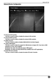
Onboard Device Configuration BIOS SETUP Main F-center Advanced Boot Power Health Security Save&Exit Onboard Device Configuration Onboard LAN Controller Onboard USB Controller USB3.0 Support Legacy USB Support Azalia ...
Onboard Device Configuration BIOS SETUP Main F-center Advanced Boot Power Health Security Save&Exit Onboard Device Configuration Onboard LAN Controller Onboard USB Controller USB3.0 Support Legacy USB Support Azalia ...
User manual
Page 39
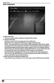
... select AHCI to get its best performance. ► SATA Port1/SATA Port2/SATA Port3/SATA Port4 Press to go to support native IDE mode. [AHCI] - BIOS SETUP SATA Configuration Main F-center Advanced Boot Power Health Security Save&Exit SATA Configuration SATA Controller(s) Onboard SATA Mode ▶ SATA Port1: Not Present ▶...
... select AHCI to get its best performance. ► SATA Port1/SATA Port2/SATA Port3/SATA Port4 Press to go to support native IDE mode. [AHCI] - BIOS SETUP SATA Configuration Main F-center Advanced Boot Power Health Security Save&Exit SATA Configuration SATA Controller(s) Onboard SATA Mode ▶ SATA Port1: Not Present ▶...

User manual
Page 40
F1: General Help F2: Previous Values F3: Optimized Defaults F4: Save & Exit ESC: Exit Version 2.15.1234. IT8732 Super IO Configuration BIOS SETUP Main F-center Advanced Boot Power Health Security Save&Exit IT8732 Super IO Configuration IT8732 Super IO Chip ▶ Serial Port 0 Configuration ▶ Serial Port 1 ...
F1: General Help F2: Previous Values F3: Optimized Defaults F4: Save & Exit ESC: Exit Version 2.15.1234. IT8732 Super IO Configuration BIOS SETUP Main F-center Advanced Boot Power Health Security Save&Exit IT8732 Super IO Configuration IT8732 Super IO Chip ▶ Serial Port 0 Configuration ▶ Serial Port 1 ...


