English Manual.
Page 6
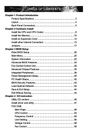
... Install the Memory 10 Install an Expansion Card 12 Install other Internal Connectors 13 Jumpers 17 Chapter 3 BIOS Setup Enter BIOS Setup 20 Main Menu 20 System Information 22 Advanced BIOS Features 24 Fox Central Control Unit 26 Advanced Chipset Features 30 Integrated Peripherals 36 Power Management Setup 40... PC Health Status 42 BIOS Security Features 43 Load Optimal Defaults 44 Save & Exit Setup 44 Exit Without Saving 44 Chapter 4 CD Instruction Utility CD ...
... Install the Memory 10 Install an Expansion Card 12 Install other Internal Connectors 13 Jumpers 17 Chapter 3 BIOS Setup Enter BIOS Setup 20 Main Menu 20 System Information 22 Advanced BIOS Features 24 Fox Central Control Unit 26 Advanced Chipset Features 30 Integrated Peripherals 36 Power Management Setup 40... PC Health Status 42 BIOS Security Features 43 Load Optimal Defaults 44 Save & Exit Setup 44 Exit Without Saving 44 Chapter 4 CD Instruction Utility CD ...

English Manual.
Page 7
...67 FOX LOGO 68 FOX DMI 69 Chapter 5 RAID Configuration RAID Configuration Introduction 72 FastBuild Driver 74 Create a RAID Driver Diskette 76 RAID Enable in BIOS 78 Select a RAID Array for Use 78 Install a New Windows XP 91 Setting Up a Non-Bootable RAID Array 95 Technical Support : Website ...com Support Support Website : http://www.foxconnchannel.com/support/online.aspx or http://www.foxconnsupport.com Worldwide E-mail Support : pcebg-cisg-support@foxconn.com CPU, Memory, VGA Compatibility Supporting Website : http://www.foxconnchannel.com/product/Motherboards/compatibility.aspx
...67 FOX LOGO 68 FOX DMI 69 Chapter 5 RAID Configuration RAID Configuration Introduction 72 FastBuild Driver 74 Create a RAID Driver Diskette 76 RAID Enable in BIOS 78 Select a RAID Array for Use 78 Install a New Windows XP 91 Setting Up a Non-Bootable RAID Array 95 Technical Support : Website ...com Support Support Website : http://www.foxconnchannel.com/support/online.aspx or http://www.foxconnsupport.com Worldwide E-mail Support : pcebg-cisg-support@foxconn.com CPU, Memory, VGA Compatibility Supporting Website : http://www.foxconnchannel.com/product/Motherboards/compatibility.aspx
English Manual.
Page 17
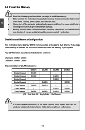
... memory of the same capacity, brand, speed, and chips be installed in your system. Single Channel DS/SS - Dual Channel - - When memory is installed, the BIOS will automatically check the memory in only one direction. DS/SS Single Channel - - It is recommended that memory of the same capacity, brand, speed, and...
... memory of the same capacity, brand, speed, and chips be installed in your system. Single Channel DS/SS - Dual Channel - - When memory is installed, the BIOS will automatically check the memory in only one direction. DS/SS Single Channel - - It is recommended that memory of the same capacity, brand, speed, and...
English Manual.
Page 19
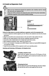
... contacts on your expansion card(s). 7. Turn on the card are completely inserted into the PCI Express x16 slot. If necessary, go to BIOS Setup to make any required BIOS changes for your computer. Remove the metal slot cover from the power outlet before installing an expansion card to correctly install your card...
... contacts on your expansion card(s). 7. Turn on the card are completely inserted into the PCI Express x16 slot. If necessary, go to BIOS Setup to make any required BIOS changes for your computer. Remove the metal slot cover from the power outlet before installing an expansion card to correctly install your card...

English Manual.
Page 23
... S3, S4 and S5 sleeping states. 1 GND POWER SENSE CONTROL CPU_FAN / SYS_FAN 16 The system can detect the chassis intrusion through the function of the BIOS Setup. INTRUDERJ 12 INTR GND Fan Headers : CPU_FAN, SYS_FAN There are two main fan headers on the chassis. The fan speed can be connected to...
... S3, S4 and S5 sleeping states. 1 GND POWER SENSE CONTROL CPU_FAN / SYS_FAN 16 The system can detect the chassis intrusion through the function of the BIOS Setup. INTRUDERJ 12 INTR GND Fan Headers : CPU_FAN, SYS_FAN There are two main fan headers on the chassis. The fan speed can be connected to...
English Manual.
Page 24
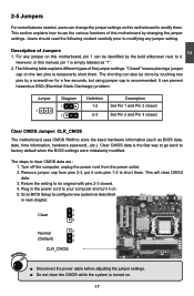
.... Turn off the computer, unplug the power cord from pins 2-3, put it onto pins 1-2 to it on the two pins to factory default when the BIOS settings were mistakenly modified. This will clear CMOS data. 3. Plug in the power cord to clear CMOS data are : 1. Normal 1 2 (Default) ... 2-3 closed Clear CMOS Jumper: CLR_CMOS The motherboard uses CMOS RAM to configure new system as BIOS data, date, time information, hardware password...etc.). Clear CMOS data is recommended. Go to BIOS Setup to store the basic hardware information (such as described in this motherboard, pin 1 can...
.... Turn off the computer, unplug the power cord from pins 2-3, put it onto pins 1-2 to it on the two pins to factory default when the BIOS settings were mistakenly modified. This will clear CMOS data. 3. Plug in the power cord to clear CMOS data are : 1. Normal 1 2 (Default) ... 2-3 closed Clear CMOS Jumper: CLR_CMOS The motherboard uses CMOS RAM to configure new system as BIOS data, date, time information, hardware password...etc.). Clear CMOS data is recommended. Go to BIOS Setup to store the basic hardware information (such as described in this motherboard, pin 1 can...

English Manual.
Page 25
... lead for each USB port; At the same time, a corresponding setting must not exceed the power supply capability (+5VSB) whether under normal condition or in BIOS as below: Set -> "Power Management Setup" -> "Resume by USB Devices" to wake up the computer from S1 sleep mode using the connected USB devices. Set...
... lead for each USB port; At the same time, a corresponding setting must not exceed the power supply capability (+5VSB) whether under normal condition or in BIOS as below: Set -> "Power Management Setup" -> "Resume by USB Devices" to wake up the computer from S1 sleep mode using the connected USB devices. Set...

English Manual.
Page 26
...(POST) process. 2. You want to run the Setup Program when the following information : ■ Enter BIOS Setup ■ Main Menu ■ System Information ■ Advanced BIOS Features ■ Fox Central Control Unit ■ Advanced Chipset Features ■ Integrated Peripherals ■ Power ...Management Setup ■ PC Health Status ■ BIOS Security Features ■ Load Optimal Defaults ■ Save & Exit Setup ■ Exit Without Saving Since BIOS could be updated some other times, the BIOS information described in the future. Detailed descriptions of this manual...
...(POST) process. 2. You want to run the Setup Program when the following information : ■ Enter BIOS Setup ■ Main Menu ■ System Information ■ Advanced BIOS Features ■ Fox Central Control Unit ■ Advanced Chipset Features ■ Integrated Peripherals ■ Power ...Management Setup ■ PC Health Status ■ BIOS Security Features ■ Load Optimal Defaults ■ Save & Exit Setup ■ Exit Without Saving Since BIOS could be updated some other times, the BIOS information described in the future. Detailed descriptions of this manual...

English Manual.
Page 27
... System Information... Copyright (C) 1985-2006, American Megatrends, Inc. ► System Information ► PC Health Status ► Advanced BIOS Features ► BIOS Security Features ► Fox Central Control Unit Load Optimal Defaults ► Advanced Chipset Features Save & Exit Setup ► Integrated ...2006, American Megatrends, Inc. ► System Information It displays the basic system configuration, such as Serial I /O devices such as BIOS ID, CPU Name, memory size plus system date, time and Floppy drive. There are boot up settings. ► Fox Central ...
... System Information... Copyright (C) 1985-2006, American Megatrends, Inc. ► System Information ► PC Health Status ► Advanced BIOS Features ► BIOS Security Features ► Fox Central Control Unit Load Optimal Defaults ► Advanced Chipset Features Save & Exit Setup ► Integrated ...2006, American Megatrends, Inc. ► System Information It displays the basic system configuration, such as Serial I /O devices such as BIOS ID, CPU Name, memory size plus system date, time and Floppy drive. There are boot up settings. ► Fox Central ...
English Manual.
Page 28
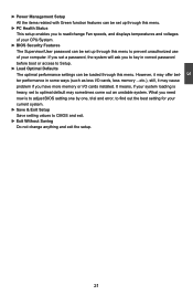
... of your computer. It means, if your system loading is heavy, set to optimal default may cause problem if you need now is to adjust BIOS setting one by one, trial and error, to find out the best setting for your current system. ► Save & Exit Setup Save setting values ...to CMOS and exit. ► Exit Without Saving Do not change Fan speeds, and displays temperatures and voltages of your CPU/System. ► BIOS Security Features The Supervisor/User password can be loaded through this menu to read/change anything and exit the setup. 21 However, it may sometimes...
... of your computer. It means, if your system loading is heavy, set to optimal default may cause problem if you need now is to adjust BIOS setting one by one, trial and error, to find out the best setting for your current system. ► Save & Exit Setup Save setting values ...to CMOS and exit. ► Exit Without Saving Do not change Fan speeds, and displays temperatures and voltages of your CPU/System. ► BIOS Security Features The Supervisor/User password can be loaded through this menu to read/change anything and exit the setup. 21 However, it may sometimes...

English Manual.
Page 29
... change system Date. [Not Detected] [Not Detected] Floppy A Halt On Keyboard Mouse Floppy [1.44 MB 31/2] [All Errors, But ...] [Disabled] [Disabled] [Disabled] Model Name BIOS ID : A7GM-S : 799F1D15 Move Enter:Select +/-/:Value F10:Save ESC:Exit F1:General Help F9:Optimized Defaults ► Date (mm:dd:yy) format. The three fields of...
... change system Date. [Not Detected] [Not Detected] Floppy A Halt On Keyboard Mouse Floppy [1.44 MB 31/2] [All Errors, But ...] [Disabled] [Disabled] [Disabled] Model Name BIOS ID : A7GM-S : 799F1D15 Move Enter:Select +/-/:Value F10:Save ESC:Exit F1:General Help F9:Optimized Defaults ► Date (mm:dd:yy) format. The three fields of...

English Manual.
Page 30
SATA 5 - SATA 6 - Secondary IDE Slave SATA 6 IDE1 - IDE1 IDE1 SATA 6 - - - - User can check this product. ► BIOS ID / BIOS Version It displays the current BIOS ID/version. SATA 5 - SATA 6 - SATA 6 IDE1 Secondary IDE Master SATA 5 IDE0 - Third IDE Slave SATA 3 SATA 3 SATA 3 SATA 3 - Mapping... if you enabled this item. ► Model Name Model name of this information and discuss with the field service people if a BIOS upgrade is depending on how many memory modules were installed in your system before powering on. ► MAC Address This item shows ...
SATA 5 - SATA 6 - Secondary IDE Slave SATA 6 IDE1 - IDE1 IDE1 SATA 6 - - - - User can check this product. ► BIOS ID / BIOS Version It displays the current BIOS ID/version. SATA 5 - SATA 6 - SATA 6 IDE1 Secondary IDE Master SATA 5 IDE0 - Third IDE Slave SATA 3 SATA 3 SATA 3 SATA 3 - Mapping... if you enabled this item. ► Model Name Model name of this information and discuss with the field service people if a BIOS upgrade is depending on how many memory modules were installed in your system before powering on. ► MAC Address This item shows ...

English Manual.
Page 31
Advanced BIOS Features IDE Detect Time Out MPS Revision PCI Latency Timer Quiet Boot Quick Boot Bootup Num-Lock Floppy Drive Seek ► Boot Device Priority ► ... to make use . Some PCI devices may be allocated to enable MPS 1.4 support if you are 32, 64, 96, 128, 160, 192, 224, 248. Advanced BIOS Features CMOS Setup Utility - MPS 1.1 was the original specification. Setting values are running an older operating system that the motherboard will actually reduce performance as...
Advanced BIOS Features IDE Detect Time Out MPS Revision PCI Latency Timer Quiet Boot Quick Boot Bootup Num-Lock Floppy Drive Seek ► Boot Device Priority ► ... to make use . Some PCI devices may be allocated to enable MPS 1.4 support if you are 32, 64, 96, 128, 160, 192, 224, 248. Advanced BIOS Features CMOS Setup Utility - MPS 1.1 was the original specification. Setting values are running an older operating system that the motherboard will actually reduce performance as...

English Manual.
Page 32
...for a floppy drive while booting up. The available settings are: On (default) and Off. ► Floppy Drive Seek This item controls whether the BIOS will appear an error message. 3 [Disabled] : Displays the normal POST messages. [Enabled] : Displays OEM customer logo instead of POST messages. ...► Quick Boot While Enabled, this option allows BIOS to skip certain tests while booting, this menu by pressing . ► Hard Disk Drives This option is used to specify the boot priority sequence...
...for a floppy drive while booting up. The available settings are: On (default) and Off. ► Floppy Drive Seek This item controls whether the BIOS will appear an error message. 3 [Disabled] : Displays the normal POST messages. [Enabled] : Displays OEM customer logo instead of POST messages. ...► Quick Boot While Enabled, this option allows BIOS to skip certain tests while booting, this menu by pressing . ► Hard Disk Drives This option is used to specify the boot priority sequence...

English Manual.
Page 33
...Enter:Select +/-/:Value F10:Save ESC:Exit F1:General Help F9:Optimized Defaults ► Super BIOS Protect To protect the system BIOS from being affected by viruses, e.g. Super BIOS Protect function protects your BIOS from virus attack, there is used to its submenu. When enabled, the system will turn ...off clock of the empty PCI slot to reduce EMI (Electromagnetic Interference). ► Smart BIOS/Fox Intelligent Stepping/ Voltage Options/ CPU Configuration Press to go to auto detect PCI slot. CIH. ► Auto Detect PCI Clock This ...
...Enter:Select +/-/:Value F10:Save ESC:Exit F1:General Help F9:Optimized Defaults ► Super BIOS Protect To protect the system BIOS from being affected by viruses, e.g. Super BIOS Protect function protects your BIOS from virus attack, there is used to its submenu. When enabled, the system will turn ...off clock of the empty PCI slot to reduce EMI (Electromagnetic Interference). ► Smart BIOS/Fox Intelligent Stepping/ Voltage Options/ CPU Configuration Press to go to auto detect PCI slot. CIH. ► Auto Detect PCI Clock This ...
English Manual.
Page 38
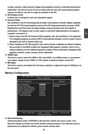
... refresh cycle while another is freed for both the ATI PCIe-based graphics card and the ATI integrated graphics processor (IGP). Enabling SurroundView in the BIOS enables the integrated UMA graphics controller, which in turn makes available up to the IGP is being accessed. Copyright (C) 1985-2006, American Megatrends, Inc. This..., please choose HDMI, if a DVI monitor is attached, please choose DVI. ► NB Azalia This item is used to select the HDMI or DVI video BIOS.
... refresh cycle while another is freed for both the ATI PCIe-based graphics card and the ATI integrated graphics processor (IGP). Enabling SurroundView in the BIOS enables the integrated UMA graphics controller, which in turn makes available up to the IGP is being accessed. Copyright (C) 1985-2006, American Megatrends, Inc. This..., please choose HDMI, if a DVI monitor is attached, please choose DVI. ► NB Azalia This item is used to select the HDMI or DVI video BIOS.

English Manual.
Page 39
... of storage cells, it's up to the memory controller and host bridge to figure out what to control EMI. Dual channel mode is enabled, the BIOS can deal with those storage cells. When disabled, the system will turn off clock on the empty DIMM slots and to reduce EMI (Electro-Magnetic...
... of storage cells, it's up to the memory controller and host bridge to figure out what to control EMI. Dual channel mode is enabled, the BIOS can deal with those storage cells. When disabled, the system will turn off clock on the empty DIMM slots and to reduce EMI (Electro-Magnetic...

English Manual.
Page 40
... be ganged as two completely independent 64-bit channels (both chan- For a description of the DRAMs associated with the channel are enabled in unganged mode, BIOS must initialize the frequency of each channel : [Channel] CKE control. Unganged channels ■ DCT channels A and B operate as a single logical 128-bit DIMM. ■ Offers...
... be ganged as two completely independent 64-bit channels (both chan- For a description of the DRAMs associated with the channel are enabled in unganged mode, BIOS must initialize the frequency of each channel : [Channel] CKE control. Unganged channels ■ DCT channels A and B operate as a single logical 128-bit DIMM. ■ Offers...

English Manual.
Page 41
It contains important information about the module's speed, size, addressing mode and various other parameters, so that BIOS programs into the memory controller is manually selected according to the set value of each DIMM. ► tRCD (RAS-to return data after the...frequency. The target clock frequency is asserted depends on a DDR2 memory module. Select [Auto] for SPD enable mode. Settings are enabled in unganged mode, BIOS must initialize the frequency of "Memory Speed Adjust". ► Memory Speed Adjust This item will not exceed the specified value listed in AM2+ CPU. ►...
It contains important information about the module's speed, size, addressing mode and various other parameters, so that BIOS programs into the memory controller is manually selected according to the set value of each DIMM. ► tRCD (RAS-to return data after the...frequency. The target clock frequency is asserted depends on a DDR2 memory module. Select [Auto] for SPD enable mode. Settings are enabled in unganged mode, BIOS must initialize the frequency of "Memory Speed Adjust". ► Memory Speed Adjust This item will not exceed the specified value listed in AM2+ CPU. ►...

English Manual.
Page 45
...] connected. SATA 6 SATA 5 - - - 3 When "SATA IDE Combined Mode" is used to enable the support for legacy USB. SATA 3 SATA 3 SATA 3 - - USB 2.0 Controller Mode [High Speed] BIOS EHCI Hand-Off [Enabled] ► USB Storage Configuration [Press Enter] Move Enter:Select +/-/:Value F10:Save ESC:Exit F1:General Help F9:Optimized Defaults ►...
...] connected. SATA 6 SATA 5 - - - 3 When "SATA IDE Combined Mode" is used to enable the support for legacy USB. SATA 3 SATA 3 SATA 3 - - USB 2.0 Controller Mode [High Speed] BIOS EHCI Hand-Off [Enabled] ► USB Storage Configuration [Press Enter] Move Enter:Select +/-/:Value F10:Save ESC:Exit F1:General Help F9:Optimized Defaults ►...


