FE 8845A & 8846A Users Manual
Page 4
8845A/8846A Users Manual 2 3 Diode Test ...1-20 Measurement Rates 1-20 Preparing the Meter for Operation 2-1 Introduction...2-3 Unpacking and Inspecting the Meter 2-3 Contacting Fluke 2-3 Storing and Shipping the Meter 2-3 Power Considerations 2-3 Selecting the Line Voltage 2-4 Replacing the Fuses 2-4 Connecting to Line Power 2-7 Turning Power-On 2-8 Adjusting the Bail 2-8 Installing the Meter in an Equipment Rack 2-8 Cleaning the Meter 2-9 Front...
8845A/8846A Users Manual 2 3 Diode Test ...1-20 Measurement Rates 1-20 Preparing the Meter for Operation 2-1 Introduction...2-3 Unpacking and Inspecting the Meter 2-3 Contacting Fluke 2-3 Storing and Shipping the Meter 2-3 Power Considerations 2-3 Selecting the Line Voltage 2-4 Replacing the Fuses 2-4 Connecting to Line Power 2-7 Turning Power-On 2-8 Adjusting the Bail 2-8 Installing the Meter in an Equipment Rack 2-8 Cleaning the Meter 2-9 Front...

FE 8845A & 8846A Users Manual
Page 5
...Meter's Default Settings 3-22 4 Making Measurements 4-1 Introduction...4-3 Selecting Function Modifiers 4-3 Activating the Secondary Display 4-3 Measuring Voltage 4-4 Measuring DC Voltage 4-4 Measuring AC Voltage 4-5 Measuring Frequency and Period 4-6 Measuring Resistance 4-7 Making a Two-Wire Resistance Measurement 4-7 Making a Four-Wire Resistance Measurement 4-8 Measuring Current 4-9 Measuring DC Current 4-10 Measuring AC Current 4-11 Measuring Capacitance (8846A... only 4-12 Measuring RTD Temperature (8846A only 4-13 Testing Continuity...
...Meter's Default Settings 3-22 4 Making Measurements 4-1 Introduction...4-3 Selecting Function Modifiers 4-3 Activating the Secondary Display 4-3 Measuring Voltage 4-4 Measuring DC Voltage 4-4 Measuring AC Voltage 4-5 Measuring Frequency and Period 4-6 Measuring Resistance 4-7 Making a Two-Wire Resistance Measurement 4-7 Making a Four-Wire Resistance Measurement 4-8 Measuring Current 4-9 Measuring DC Current 4-10 Measuring AC Current 4-11 Measuring Capacitance (8846A... only 4-12 Measuring RTD Temperature (8846A only 4-13 Testing Continuity...

FE 8845A & 8846A Users Manual
Page 13
... with variable reference impedance and audio power measurement capability • Input terminals on both front and rear panels of the meter • Closed-case calibration (no internal calibration adjustments) Manual Set The manual set for these multimeters include a carrying handle... measurements • Extended 10 Ω and 1 GΩ ranges (8846A Only) • Frequency measurements to 300 kHz (8846A to clarify the differences between these two models. The Programmers Manual covers operating the Meter from the front panel. Their full complement of a Users Manual and Programmers...
... with variable reference impedance and audio power measurement capability • Input terminals on both front and rear panels of the meter • Closed-case calibration (no internal calibration adjustments) Manual Set The manual set for these multimeters include a carrying handle... measurements • Extended 10 Ω and 1 GΩ ranges (8846A Only) • Frequency measurements to 300 kHz (8846A to clarify the differences between these two models. The Programmers Manual covers operating the Meter from the front panel. Their full complement of a Users Manual and Programmers...
FE 8845A & 8846A Users Manual
Page 14
...result in accordance with and around electricity. 1-4 Chapter 2 "Preparing for the 8845A and 8846A Digital Multimeters (hereafter referred to operate the Meter effectively. To use the Meter correctly and safely, read the information under "Safety Information" before attempting to make electrical... or warnings given throughout this Manual This is the Users Manual for Operation" provides information on setting the Meter's line voltage, connecting it is divided into the following chapters: Chapter 1 "Introduction and Specifications" provides information on how...
...result in accordance with and around electricity. 1-4 Chapter 2 "Preparing for the 8845A and 8846A Digital Multimeters (hereafter referred to operate the Meter effectively. To use the Meter correctly and safely, read the information under "Safety Information" before attempting to make electrical... or warnings given throughout this Manual This is the Users Manual for Operation" provides information on setting the Meter's line voltage, connecting it is divided into the following chapters: Chapter 1 "Introduction and Specifications" provides information on how...

FE 8845A & 8846A Users Manual
Page 15
...capacitors before testing resistance, continuity, diodes, or capacitance. • Before measuring current, check the Meter's fuses and turn OFF power to the circuit. • When servicing the Meter, use the Meter if it . These voltages pose a shock hazard. • Use only the replacement fuse(s) specified... • Do not apply more than the rated voltage, as marked on the Meter, between the terminals or between any unintended operation. • Have the Meter serviced only by the Meter might be impaired. Do not use only specified replacement parts. 1-5 when disconnecting, ...
...capacitors before testing resistance, continuity, diodes, or capacitance. • Before measuring current, check the Meter's fuses and turn OFF power to the circuit. • When servicing the Meter, use the Meter if it . These voltages pose a shock hazard. • Use only the replacement fuse(s) specified... • Do not apply more than the rated voltage, as marked on the Meter, between the terminals or between any unintended operation. • Have the Meter serviced only by the Meter might be impaired. Do not use only specified replacement parts. 1-5 when disconnecting, ...

FE 8845A & 8846A Users Manual
Page 16
... memory elements listed in this product as unsorted municipal waste. Press M. 2. 8845A/8846A Users Manual Symbols Table 1-2 is a list of safety and electrical symbols that appear on the Meter or in Table 1-3: 1. Select the MANAGE MEMORY soft key. 3. Safety and ... Symbol Description W Risk of this manual. Contact Fluke or a qualified recycler for disposal Instrument Security Procedures This section describes the Meter's memory elements and the procedures for clearing them. Volatile Memory Table 1-3 lists the Meter's volatile memory elements. Select the ERASE MEMORY soft...
... memory elements listed in this product as unsorted municipal waste. Press M. 2. 8845A/8846A Users Manual Symbols Table 1-2 is a list of safety and electrical symbols that appear on the Meter or in Table 1-3: 1. Select the MANAGE MEMORY soft key. 3. Safety and ... Symbol Description W Risk of this manual. Contact Fluke or a qualified recycler for disposal Instrument Security Procedures This section describes the Meter's memory elements and the procedures for clearing them. Volatile Memory Table 1-3 lists the Meter's volatile memory elements. Select the ERASE MEMORY soft...

FE 8845A & 8846A Users Manual
Page 17
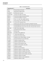
... Accessories Non Volatile Memory Table 1-4 lists the Meter's non-volatile memory elements. Select the ERASE MEMORY soft key. Accessories Table 1-3 lists the available accessories for connecting flash memory modules up to 2 Gigabytes to the 8846A: 1. Select the MANAGE MEMORY soft key. ...3. Table 1-5. Note The 4 MB non-volatile memory element is not usable and cannot be cleared by the user. Select the MANAGE MEMORY soft key. 3. FPGA hardware setup, application program storage, calibration constants. Accessories Model/Fluke...
... Accessories Non Volatile Memory Table 1-4 lists the Meter's non-volatile memory elements. Select the ERASE MEMORY soft key. Accessories Table 1-3 lists the available accessories for connecting flash memory modules up to 2 Gigabytes to the 8846A: 1. Select the MANAGE MEMORY soft key. ...3. Table 1-5. Note The 4 MB non-volatile memory element is not usable and cannot be cleared by the user. Select the MANAGE MEMORY soft key. 3. FPGA hardware setup, application program storage, calibration constants. Accessories Model/Fluke...
FE 8845A & 8846A Users Manual
Page 18
...) FlukeView Forms, Basic Software FlukeView Forms, Software Upgrade - Shielded IEEE 488 one-meter (39.4 inches) cable, with plug and jack at each end. 8845A/8846A Users Manual Table 1-3. Shielded IEEE 488 two-meter (78.8 inches) cable, with data Agreement, Calibration, Z540 Traceable, without data Agreement..., Calibration, Traceable, without data Agreement, Calibration, Z540 Traceable, with plug and jack at each end. Accessories (cont) Model/Fluke PN Description TL910 TL80A TL2X4W-PT TL2X4W-TWZ 6262-02 6263-02 803293 943121 884X-RTD Y8846 Y8021 Y8022 884X-USB RS43 884X...
...) FlukeView Forms, Basic Software FlukeView Forms, Software Upgrade - Shielded IEEE 488 one-meter (39.4 inches) cable, with plug and jack at each end. 8845A/8846A Users Manual Table 1-3. Shielded IEEE 488 two-meter (78.8 inches) cable, with data Agreement, Calibration, Z540 Traceable, without data Agreement..., Calibration, Traceable, without data Agreement, Calibration, Z540 Traceable, with plug and jack at each end. Accessories (cont) Model/Fluke PN Description TL910 TL80A TL2X4W-PT TL2X4W-TWZ 6262-02 6263-02 803293 943121 884X-RTD Y8846 Y8021 Y8022 884X-USB RS43 884X...

FE 8845A & 8846A Users Manual
Page 19
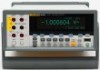
1 Introduction and Specifications General Specifications General Specifications Power Voltage 100 V Setting 90 V to 110 V 120 V Setting 108 V to 132 V 220 V Setting 198 V to 242 V 240 V Setting 216 V to 264 V Frequency 47 Hz to 28 °C Power Consumption 28 VA peak (12 Watt average) Dimensions Height 88 mm (3.46 in.) Width 217 mm (8.56 in.) Depth 297 mm (11.7 in.) Weight 3.6 kg (8.0 Ibs.) Shipping Weight 5.0 kg (11.0 lbs) Display Vacuum Fluorescent Display, dot matrix Environment Temperature Operating 0 °C to 55 °C Storage 40 °C to 70 °C Warm Up 1 hour to ...
1 Introduction and Specifications General Specifications General Specifications Power Voltage 100 V Setting 90 V to 110 V 120 V Setting 108 V to 132 V 220 V Setting 198 V to 242 V 240 V Setting 216 V to 264 V Frequency 47 Hz to 28 °C Power Consumption 28 VA peak (12 Watt average) Dimensions Height 88 mm (3.46 in.) Width 217 mm (8.56 in.) Depth 297 mm (11.7 in.) Weight 3.6 kg (8.0 Ibs.) Shipping Weight 5.0 kg (11.0 lbs) Display Vacuum Fluorescent Display, dot matrix Environment Temperature Operating 0 °C to 55 °C Storage 40 °C to 70 °C Warm Up 1 hour to ...

FE 8845A & 8846A Users Manual
Page 20
...of 1 or greater with dc filter on all ranges except 1000 V dc, 1000 V ac (8846A), 750 V ac (8845A), Diode, and 10 A ranges Remote Interfaces RS-232 (RS-232 to USB cable available to connect the Meter to a PC USB port. Input Characteristics Range 100 mV 1 V 10 V 100 V 1000 ...8486; is enabled. 24-hour specifications are affected by source impedance, cable dielectric characteristics, and input signal changes. 8845A/8846A Users Manual Memory 8845A 10,000 measurements, Internal only 8846A 10,000 measurements, Internal and up at 50 or 60 Hz ± 0.1 % (1 kΩ unbalance) Normal ...
...of 1 or greater with dc filter on all ranges except 1000 V dc, 1000 V ac (8846A), 750 V ac (8845A), Diode, and 10 A ranges Remote Interfaces RS-232 (RS-232 to USB cable available to connect the Meter to a PC USB port. Input Characteristics Range 100 mV 1 V 10 V 100 V 1000 ...8486; is enabled. 24-hour specifications are affected by source impedance, cable dielectric characteristics, and input signal changes. 8845A/8846A Users Manual Memory 8845A 10,000 measurements, Internal only 8846A 10,000 measurements, Internal and up at 50 or 60 Hz ± 0.1 % (1 kΩ unbalance) Normal ...

FE 8845A & 8846A Users Manual
Page 31
Chapter 2 Preparing the Meter for Operation Title Page Introduction...2-3 Unpacking and Inspecting the Meter 2-3 Contacting Fluke 2-3 Storing and Shipping the Meter 2-3 Power Considerations 2-3 Selecting the Line Voltage 2-4 Replacing the Fuses 2-4 Line-Power Fuse 2-4 Current-Input Fuses 2-5 Connecting to Line Power 2-7 Turning Power-On 2-8 Adjusting the Bail 2-8 Installing the Meter in an Equipment Rack 2-8 Cleaning the Meter 2-9 2-1
Chapter 2 Preparing the Meter for Operation Title Page Introduction...2-3 Unpacking and Inspecting the Meter 2-3 Contacting Fluke 2-3 Storing and Shipping the Meter 2-3 Power Considerations 2-3 Selecting the Line Voltage 2-4 Replacing the Fuses 2-4 Line-Power Fuse 2-4 Current-Input Fuses 2-5 Connecting to Line Power 2-7 Turning Power-On 2-8 Adjusting the Bail 2-8 Installing the Meter in an Equipment Rack 2-8 Cleaning the Meter 2-9 2-1

FE 8845A & 8846A Users Manual
Page 33
...similar shock isolation. Place the bag into the cushioning material inside a sealed bag. If the Meter is shipped, use with a line voltage determined at www.fluke.com. Unpacking and Inspecting the Meter Every care is taken in perfect condition. Save the container and the packing material in case you... voltage, connecting an appropriate line power cord, and turning on the line voltage that is missing, contact both the carrier and Fluke immediately. The Meter is information on power distribution standards found throughout the world, and must be visible external damage to return the...
...similar shock isolation. Place the bag into the cushioning material inside a sealed bag. If the Meter is shipped, use with a line voltage determined at www.fluke.com. Unpacking and Inspecting the Meter Every care is taken in perfect condition. Save the container and the packing material in case you... voltage, connecting an appropriate line power cord, and turning on the line voltage that is missing, contact both the carrier and Fluke immediately. The Meter is information on power distribution standards found throughout the world, and must be visible external damage to return the...
FE 8845A & 8846A Users Manual
Page 34
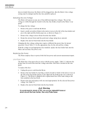
... do not use makeshift fuses or short-circuit the fuse holder. Use only Fluke fuses 2-4 Changing the line voltage setting may require a different line-power fuse for the selected line voltage. Line-Power Fuse The Meter has a line-power fuse in series with a replacement fuse of the same...back into , then the Meter's line voltage setting must be changed and the line fuse possibly replaced. Replacing the Fuses The Meter employs fuses to the right until the preferred voltage rating faces outward. 5. 8845A/8846A Users Manual does not match the power the Meter will operate on any one...
... do not use makeshift fuses or short-circuit the fuse holder. Use only Fluke fuses 2-4 Changing the line voltage setting may require a different line-power fuse for the selected line voltage. Line-Power Fuse The Meter has a line-power fuse in series with a replacement fuse of the same...back into , then the Meter's line voltage setting must be changed and the line fuse possibly replaced. Replacing the Fuses The Meter employs fuses to the right until the preferred voltage rating faces outward. 5. 8845A/8846A Users Manual does not match the power the Meter will operate on any one...

FE 8845A & 8846A Users Manual
Page 35
...8226; The 100 mA input is protected by a fuse (F2) rated at 440 mA, 1000 V (fast blow), 10,000 A minimum breaking capacity (Fluke Part No. 943121). • The 10 A input is good, the Meter will read less than 200 Ω. To test for Operation Power Considerations Table 2-1. With the... connector. If the fuse is blown, the Meter will read overload. 4. Press N. 3. If the fuse is protected by a fuse (F1) rated at 11 A, 1000 V (fast blow), 10,000 A minimum breaking capacity (Fluke Part No. 803293). Remove the probe from Fluke. Line Voltage to Fuse Rating Line Voltage Selection...
...8226; The 100 mA input is protected by a fuse (F2) rated at 440 mA, 1000 V (fast blow), 10,000 A minimum breaking capacity (Fluke Part No. 943121). • The 10 A input is good, the Meter will read less than 200 Ω. To test for Operation Power Considerations Table 2-1. With the... connector. If the fuse is blown, the Meter will read overload. 4. Press N. 3. If the fuse is protected by a fuse (F1) rated at 11 A, 1000 V (fast blow), 10,000 A minimum breaking capacity (Fluke Part No. 803293). Remove the probe from Fluke. Line Voltage to Fuse Rating Line Voltage Selection...

FE 8845A & 8846A Users Manual
Page 36
...the fuses while aligning the catches with one having the appropriate rating. 6. Turn the Meter off, unplug the power cord from the fuse compartment. 5. Replace the protective cover by pushing it from the Meter, and remove all test leads. 2. Fuses F1 F2 Bottom front left corner Figure... tightening the retaining screw. If the fuse is good, the Meter will read less than 1 Ω. Remove the defective fuse, and replace with the holes in Figure 2-2. 4. 8845A/8846A Users Manual If the fuse is blown, the Meter will read overload. To replace the Current Input fuses, 1.
...the fuses while aligning the catches with one having the appropriate rating. 6. Turn the Meter off, unplug the power cord from the fuse compartment. 5. Replace the protective cover by pushing it from the Meter, and remove all test leads. 2. Fuses F1 F2 Bottom front left corner Figure... tightening the retaining screw. If the fuse is good, the Meter will read less than 1 Ω. Remove the defective fuse, and replace with the holes in Figure 2-2. 4. 8845A/8846A Users Manual If the fuse is blown, the Meter will read overload. To replace the Current Input fuses, 1.
FE 8845A & 8846A Users Manual
Page 37
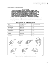
... North America Universal Euro United Kingdom Switzerland Australia South Africa Table 2-2. Do not use a two-conductor adapter or extension cord; Connect the Meter to the correct position, and then that the correct fuse for Operation Connecting to Line Power Connecting to Line Power XWWarning To avoid shock ...Figure 2-3. First verify that the line voltage selection is installed. this will break the protective ground connection. Line Power Cord Types Available from Fluke alh3.eps 2-7 2 Preparing the Meter for that line voltage is set to a properly grounded three-prong outlet.
... North America Universal Euro United Kingdom Switzerland Australia South Africa Table 2-2. Do not use a two-conductor adapter or extension cord; Connect the Meter to the correct position, and then that the correct fuse for Operation Connecting to Line Power Connecting to Line Power XWWarning To avoid shock ...Figure 2-3. First verify that the line voltage selection is installed. this will break the protective ground connection. Line Power Cord Types Available from Fluke alh3.eps 2-7 2 Preparing the Meter for that line voltage is set to a properly grounded three-prong outlet.

FE 8845A & 8846A Users Manual
Page 38
...bench-top use, the Meter's bail or handle is depressed. Then refer to the instructions provided with proper earth ground. In preparation for rack mounting, remove the bail (see the "Adjusting the Bail" section above) and the front and rear protective boots. 8845A/8846A Users Manual Turning Power-On... XW Warning To avoid electric shock, connect the Meter's power cord to a power receptacle with the Rack Mount Kit to mount the...
...bench-top use, the Meter's bail or handle is depressed. Then refer to the instructions provided with proper earth ground. In preparation for rack mounting, remove the bail (see the "Adjusting the Bail" section above) and the front and rear protective boots. 8845A/8846A Users Manual Turning Power-On... XW Warning To avoid electric shock, connect the Meter's power cord to a power receptacle with the Rack Mount Kit to mount the...

FE 8845A & 8846A Users Manual
Page 39
Do not use aromatic hydrocarbons, chlorinated solvents, or methanolbased fluids when wiping down with a cloth lightly dampened with water or a mild detergent. If the Meter requires cleaning, wipe it down the meter. 2-9 W Caution To avoid damaging the Meter's housing, do not apply solvents to the Meter, never get water inside the meter. 2 Preparing the Meter for Operation Cleaning the Meter Cleaning the Meter XW Warning To avoid electric shock or damage to the Meter.
Do not use aromatic hydrocarbons, chlorinated solvents, or methanolbased fluids when wiping down with a cloth lightly dampened with water or a mild detergent. If the Meter requires cleaning, wipe it down the meter. 2-9 W Caution To avoid damaging the Meter's housing, do not apply solvents to the Meter, never get water inside the meter. 2 Preparing the Meter for Operation Cleaning the Meter Cleaning the Meter XW Warning To avoid electric shock or damage to the Meter.

FE 8845A & 8846A Users Manual
Page 41
...and Indicators 3-3 Front-Panel Feature Descriptions 3-3 Display Panel 3-4 Rear-Panel Connectors 3-6 Adjusting the Meter's Range 3-7 Navigating the Front-Panel Menu 3-7 Configuring the Meter for a Measurement 3-7 Setting the Display Resolution 3-7 Setting the AC Signal Filter 3-8 Setting ...Continuity Resistance Threshold and Diode Test Parameters .......... 3-8 Setting the Default Temperature Scale (8846A Only 3-9 Enabling Automatic Input ...
...and Indicators 3-3 Front-Panel Feature Descriptions 3-3 Display Panel 3-4 Rear-Panel Connectors 3-6 Adjusting the Meter's Range 3-7 Navigating the Front-Panel Menu 3-7 Configuring the Meter for a Measurement 3-7 Setting the Display Resolution 3-7 Setting the AC Signal Filter 3-8 Setting ...Continuity Resistance Threshold and Diode Test Parameters .......... 3-8 Setting the Default Temperature Scale (8846A Only 3-9 Enabling Automatic Input ...

FE 8845A & 8846A Users Manual
Page 42
8845A/8846A Users Manual Setting the Meter's Date and Time 3-21 Configuring the Remote Interface 3-22 Checking the Meter's Calibration Date 3-22 Resetting the Meter's Default Settings 3-22 3-2
8845A/8846A Users Manual Setting the Meter's Date and Time 3-21 Configuring the Remote Interface 3-22 Checking the Meter's Calibration Date 3-22 Resetting the Meter's Default Settings 3-22 3-2


