Fluke 741B, 743B, and 744 Process Calibrator Datasheet
Page 1
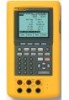
...Calibrators C789 See page 44 80PK-8 See page 42 Fluke-700Pxx See page 27 80PK-25 See page 42 TL220 See page 39 Included accessories TL224 Industrial Test Leads (2 sets), AC220 Test Clips (2 sets), TP220 Test Probes, BP7217 Battery Pack, BC7217 Battery Charger, ...storage capacity for calibration of calibrations and procedures. Here is often misunderstood. Ordering information Fluke-741B Documenting Process Calibrator Fluke-743B Documenting Process Calibrator Fluke-744 Documenting Process Calibrator For more information, go to monitor, control, and calibrate HART instrumentation...
...Calibrators C789 See page 44 80PK-8 See page 42 Fluke-700Pxx See page 27 80PK-25 See page 42 TL220 See page 39 Included accessories TL224 Industrial Test Leads (2 sets), AC220 Test Clips (2 sets), TP220 Test Probes, BP7217 Battery Pack, BC7217 Battery Charger, ...storage capacity for calibration of calibrations and procedures. Here is often misunderstood. Ordering information Fluke-741B Documenting Process Calibrator Fluke-743B Documenting Process Calibrator Fluke-744 Documenting Process Calibrator For more information, go to monitor, control, and calibrate HART instrumentation...
Fluke 744 Users Manual
Page 13
...If the calibrator is damaged or something is missing, contact the place of this manual. • TL24 industrial test leads (two sets) • AC20 test clips (two sets) • TP20 test probes (one set) • HART interface cable • BP7235 rechargeable nickel-metal hydride pack • ... connections (two included, PN 944632) Documenting Process Calibrator Standard Equipment • 744 Users Manual English (PN 691287) French (PN 691300) German (PN 691311) Italian (PN 691318) Spanish (PN 691303) • 744 HART® Mode Users Guide English (PN 691292) French (PN 691326) German...
...If the calibrator is damaged or something is missing, contact the place of this manual. • TL24 industrial test leads (two sets) • AC20 test clips (two sets) • TP20 test probes (one set) • HART interface cable • BP7235 rechargeable nickel-metal hydride pack • ... connections (two included, PN 944632) Documenting Process Calibrator Standard Equipment • 744 Users Manual English (PN 691287) French (PN 691300) German (PN 691311) Italian (PN 691318) Spanish (PN 691303) • 744 HART® Mode Users Guide English (PN 691292) French (PN 691326) German...
Fluke 744 Users Manual
Page 15
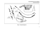
ENTER V RTD mA mA V RTD SOURCE 30V MAX MEAS 300V MAX TC Strap Figure 1. AC20 Test Clip (2 Red and 2 Black) TL24 Test Leads (2 Red and 2 Black) TP20 Test Probe (1 Red and 1 Black) Jumper (2 Black) Documenting Process Calibrator Standard Equipment V 7 4 V Hz 8 9 5 6 TC RTD CLEAR ( ZERO) 1 2 3 0 . Standard Equipment ot01f.eps 5
ENTER V RTD mA mA V RTD SOURCE 30V MAX MEAS 300V MAX TC Strap Figure 1. AC20 Test Clip (2 Red and 2 Black) TL24 Test Leads (2 Red and 2 Black) TP20 Test Probe (1 Red and 1 Black) Jumper (2 Black) Documenting Process Calibrator Standard Equipment V 7 4 V Hz 8 9 5 6 TC RTD CLEAR ( ZERO) 1 2 3 0 . Standard Equipment ot01f.eps 5
Fluke 744 Users Manual
Page 18
... it operates abnormally. Replace damaged test leads before you connect the live test lead first. • Replace the battery as soon as there is damaged. The possibility of false readings can lead to the insulation surrounding the connectors...744 Users Manual Safety Information (cont) A Warning identifies conditions and actions that may be impaired. Pay particular attention to electric shock and personal injury. 8 Check test lead continuity. Protection may damage the calibrator or the equipment under test before testing resistance or continuity. • Inspect the test leads...
... it operates abnormally. Replace damaged test leads before you connect the live test lead first. • Replace the battery as soon as there is damaged. The possibility of false readings can lead to the insulation surrounding the connectors...744 Users Manual Safety Information (cont) A Warning identifies conditions and actions that may be impaired. Pay particular attention to electric shock and personal injury. 8 Check test lead continuity. Protection may damage the calibrator or the equipment under test before testing resistance or continuity. • Inspect the test leads...
Fluke 744 Users Manual
Page 19
..., make sure the process pressure line is shut off and depressurized before you connect it to or disconnect it from the pressure module. • Disconnect test leads before changing to another measure or source function. Documenting Process Calibrator Safety Information • When servicing the calibrator, use only specified replacement parts. • Do... with any terminal and earth ground. • When using probes, keep your measurements. 9 Safety Information (cont) Warning (cont) • Do not apply more than the Fluke model BE9005 Battery Eliminator.
..., make sure the process pressure line is shut off and depressurized before you connect it to or disconnect it from the pressure module. • Disconnect test leads before changing to another measure or source function. Documenting Process Calibrator Safety Information • When servicing the calibrator, use only specified replacement parts. • Do... with any terminal and earth ground. • When using probes, keep your measurements. 9 Safety Information (cont) Warning (cont) • Do not apply more than the Fluke model BE9005 Battery Eliminator.
Fluke 744 Users Manual
Page 40
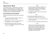
...Fluke. Connect the calibrator to the circuit to be tested. 2. Before you use them, how you zero them, what types of pressure modules are measuring to be tested...If you expect the frequency you are available from the circuit to test continuity: 1. The word Open appears when the resistance is less ... wWarning To avoid a violent release of this manual. Connect the test leads as described in Figure 10, depending on the display when the ...below 20 Hz, press d to select a frequency range. Testing Continuity When testing continuity, the beeper sounds and the word Short appears on ...
...Fluke. Connect the calibrator to the circuit to be tested. 2. Before you use them, how you zero them, what types of pressure modules are measuring to be tested...If you expect the frequency you are available from the circuit to test continuity: 1. The word Open appears when the resistance is less ... wWarning To avoid a violent release of this manual. Connect the test leads as described in Figure 10, depending on the display when the ...below 20 Hz, press d to select a frequency range. Testing Continuity When testing continuity, the beeper sounds and the word Short appears on ...
Fluke 744 Users Manual
Page 56
If the calibrator is not in Figure 16, depending on the display. Connect the test leads as follows: 1. Press M for current, v for dc voltage, h for frequency, or q for the g symbol to change the output value enter a new value and press e. For ...-symmetric sine or positive square wave. Enter the desired output value, then press e. The amplitude you use the Loop Power function accessible from Setup mode. 744 Users Manual Using Source Mode The operating mode (i.e., MEASURE, SOURCE) is shown in which the calibrator is powering a process instrument. You must be in the...
If the calibrator is not in Figure 16, depending on the display. Connect the test leads as follows: 1. Press M for current, v for dc voltage, h for frequency, or q for the g symbol to change the output value enter a new value and press e. For ...-symmetric sine or positive square wave. Enter the desired output value, then press e. The amplitude you use the Loop Power function accessible from Setup mode. 744 Users Manual Using Source Mode The operating mode (i.e., MEASURE, SOURCE) is shown in which the calibrator is powering a process instrument. You must be in the...
Fluke 744 Users Manual
Page 65
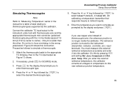
... and Ref. Temp. After you want to simulate as Figure 13 shows. 2. Note If you to enter thermocouple type. 4. Junc. Attach the thermocouple leads to the appropriate TC miniplug, then to simulate a thermocouple: 1. Press t for this by e to select Linear T (default), or Linear mV, ... Thermocouples Note Refer to "Measuring Temperature" earlier in the wrong polarization. Connect the calibrator TC input/output to the instrument under test with thermocouple wire and the appropriate thermocouple mini-connector (polarized thermocouple plug with flat, in-line blades spaced 7.9 mm [0.312 ...
... and Ref. Temp. After you want to simulate as Figure 13 shows. 2. Note If you to enter thermocouple type. 4. Junc. Attach the thermocouple leads to the appropriate TC miniplug, then to simulate a thermocouple: 1. Press t for this by e to select Linear T (default), or Linear mV, ... Thermocouples Note Refer to "Measuring Temperature" earlier in the wrong polarization. Connect the calibrator TC input/output to the instrument under test with thermocouple wire and the appropriate thermocouple mini-connector (polarized thermocouple plug with flat, in-line blades spaced 7.9 mm [0.312 ...
Fluke 744 Users Manual
Page 78
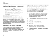
... found data for a thermocouple temperature transmitter. and 2 Pt. In this same method. Press m. 4. Connect the test leads to generate as shown in calibration routine is activated when you press the As Found softkey. (As Found data are developed ..., you use this case the calibrator is simulating the output of a transmitter before you press As Found. 1. If necessary, press M for instructions. 744 Users Manual Calibrating a Process Instrument Note To calibrate a HART-capable transmitter using a host computer and compatible application software. The way you set up the...
... found data for a thermocouple temperature transmitter. and 2 Pt. In this same method. Press m. 4. Connect the test leads to generate as shown in calibration routine is activated when you press the As Found softkey. (As Found data are developed ..., you use this case the calibrator is simulating the output of a transmitter before you press As Found. 1. If necessary, press M for instructions. 744 Users Manual Calibrating a Process Instrument Note To calibrate a HART-capable transmitter using a host computer and compatible application software. The way you set up the...
Fluke 744 Users Manual
Page 87
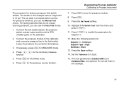
... set state is a closed switch contact. The procedure for Setpoint 1. 12. The switch in this example sets at a high limit of 10 psi. Connect the test leads between the pressure switch contact output and the mA Ω RTD (middle) jacks on the calibrator. 2. Press c to 0.5 psi. 15. Switch... Test from the menu and press e. 11. Set the Tolerance to zero the pressure module. 8. The next parameters, Deadband Min and Deadband Max, are optional. Press ...
... set state is a closed switch contact. The procedure for Setpoint 1. 12. The switch in this example sets at a high limit of 10 psi. Connect the test leads between the pressure switch contact output and the mA Ω RTD (middle) jacks on the calibrator. 2. Press c to 0.5 psi. 15. Switch... Test from the menu and press e. 11. Set the Tolerance to zero the pressure module. 8. The next parameters, Deadband Min and Deadband Max, are optional. Press ...
Fluke 744 Users Manual
Page 88
...back down until the switch resets. Results from the As Found and As Left tests are saved in the calibrator memory for limit switches that respond to the trip point. 20. 744 Users Manual 16. Press the Manual Test softkey. 19. When the switch sets, slowly bring the pressure up to ...limit switch as you do a 2 Pt. Now press the Adjust softkey if you simply follow the prompts on the display for testing the first switch, changing test leads, and testing the second limit switch. 78 The procedure for later viewing or uploading. When you want to Trip Cont by cycling through the ...
...back down until the switch resets. Results from the As Found and As Left tests are saved in the calibrator memory for limit switches that respond to the trip point. 20. 744 Users Manual 16. Press the Manual Test softkey. 19. When the switch sets, slowly bring the pressure up to ...limit switch as you do a 2 Pt. Now press the Adjust softkey if you simply follow the prompts on the display for testing the first switch, changing test leads, and testing the second limit switch. 78 The procedure for later viewing or uploading. When you want to Trip Cont by cycling through the ...
Fluke 744 Users Manual
Page 89
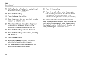
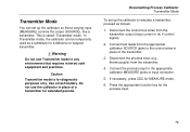
... or suspect transmitter. Use a fresh battery. In Transmitter mode, the calibrator can set up the calibrator so that requires intrinsic safe equipment and practices. Connect test leads from the transmitter. 4. Transmitter Mode You can be temporarily used as follows: 1. Press the appropriate function key for MEASURE mode. 6. Disconnect the process input (e.g., thermocouple...
... or suspect transmitter. Use a fresh battery. In Transmitter mode, the calibrator can set up the calibrator so that requires intrinsic safe equipment and practices. Connect test leads from the transmitter. 4. Transmitter Mode You can be temporarily used as follows: 1. Press the appropriate function key for MEASURE mode. 6. Disconnect the process input (e.g., thermocouple...
Fluke 744 Users Manual
Page 98
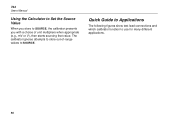
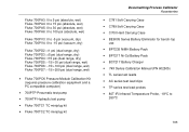
Quick Guide to Applications The following figures show test lead connections and which calibrator function to use for many different applications. 88 The calibrator ignores attempts to store out-of unit multipliers when appropriate (e.g., mV or V), then starts sourcing that value. 744 Users Manual Using the Calculator to Set the Source Value When you store to SOURCE, the calibrator presents you with a choice of -range values to SOURCE.
Quick Guide to Applications The following figures show test lead connections and which calibrator function to use for many different applications. 88 The calibrator ignores attempts to store out-of unit multipliers when appropriate (e.g., mV or V), then starts sourcing that value. 744 Users Manual Using the Calculator to Set the Source Value When you store to SOURCE, the calibrator presents you with a choice of -range values to SOURCE.
Fluke 744 Users Manual
Page 113
... Module Calibration Kit (requires pressure calibration equipment and a PC compatible computer) • 700PTP Pneumatic test pump • 700HTP Hydraulic test pump • Fluke-700TC1 TC miniplug kit • Fluke-700TC2 TC miniplug kit Documenting Process Calibrator Accessories • C781 Soft Carrying Case • C789 Soft...-Cd Battery Pack • BC7217 Battery Charger • 74X Series Calibration Manual (PN 602505) • TL series test leads • AC series test lead clips • TP series test lead probes • 80T-IR Infrared Temperature Probe, -18°C to 260°C 103
... Module Calibration Kit (requires pressure calibration equipment and a PC compatible computer) • 700PTP Pneumatic test pump • 700HTP Hydraulic test pump • Fluke-700TC1 TC miniplug kit • Fluke-700TC2 TC miniplug kit Documenting Process Calibrator Accessories • C781 Soft Carrying Case • C789 Soft...-Cd Battery Pack • BC7217 Battery Charger • 74X Series Calibration Manual (PN 602505) • TL series test leads • AC series test lead clips • TP series test lead probes • 80T-IR Infrared Temperature Probe, -18°C to 260°C 103


