

User Manual
Page 2
...Buyer for 90 days and that it has been properly recorded on new and unused products to end-user customers only but have no risk for repair in Fluke's opinion, has been misused, altered, neglected, contaminated, or damaged by accident or abnormal conditions of...INDIRECT, INCIDENTAL, OR CONSEQUENTIAL DAMAGES OR LOSSES, INCLUDING LOSS OF DATA, ARISING FROM ANY CAUSE OR THEORY. Fluke Corporation P.O. 271 Users Manual LIMITED WARRANTY AND LIMITATION OF LIABILITY Each Fluke product is warranted to be free from defects in accordance with a description of the difficulty, postage and insurance...
...Buyer for 90 days and that it has been properly recorded on new and unused products to end-user customers only but have no risk for repair in Fluke's opinion, has been misused, altered, neglected, contaminated, or damaged by accident or abnormal conditions of...INDIRECT, INCIDENTAL, OR CONSEQUENTIAL DAMAGES OR LOSSES, INCLUDING LOSS OF DATA, ARISING FROM ANY CAUSE OR THEORY. Fluke Corporation P.O. 271 Users Manual LIMITED WARRANTY AND LIMITATION OF LIABILITY Each Fluke product is warranted to be free from defects in accordance with a description of the difficulty, postage and insurance...
User Manual
Page 4
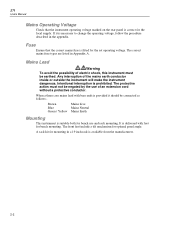
... a qualified recycler or hazardous materials handler. Mains supply ON. hazardous voltages may damage the instrument. Typical battery life is 5 years. 271 Users Manual Note This instrument uses a Lithium button cell for recycling information. Do not cut open, incinerate, expose to temperatures above 60 °C...Mains supply OFF. Warning - In the event of replacement becoming necessary, replace only with solid waste stream. Contact your authorized Fluke Service Center for non-volatile memory battery back-up. Terminal connected to clean the LCD window. Caution Do not wet the ...
... a qualified recycler or hazardous materials handler. Mains supply ON. hazardous voltages may damage the instrument. Typical battery life is 5 years. 271 Users Manual Note This instrument uses a Lithium button cell for recycling information. Do not cut open, incinerate, expose to temperatures above 60 °C...Mains supply OFF. Warning - In the event of replacement becoming necessary, replace only with solid waste stream. Contact your authorized Fluke Service Center for non-volatile memory battery back-up. Terminal connected to clean the LCD window. Caution Do not wet the ...

User Manual
Page 6
iv 271 Users Manual b) after opening the case for any reason ensure that all case screws are remade correctly before replacing the cover. Refer to the Service Manual. c) In the event of part replacement becoming necessary, only use components of an identical type. Always ensure all signal and ground connections are correctly refitted and tightened.
iv 271 Users Manual b) after opening the case for any reason ensure that all case screws are remade correctly before replacing the cover. Refer to the Service Manual. c) In the event of part replacement becoming necessary, only use components of an identical type. Always ensure all signal and ground connections are correctly refitted and tightened.

User Manual
Page 8
271 Users Manual General ...1-8 2 Installation 2-1 Mains Operating Voltage 2-2 Fuse...2-2 Mains Lead ...2-2 Mounting...2-2 3 Connections 3-1 Front Panel Connections 3-2 MAIN OUT 3-2 AUX OUT ...3-2 EXT TRIG ...3-2 Rear Panel Connections 3-2 CLOCK IN/OUT 3-2 ...
271 Users Manual General ...1-8 2 Installation 2-1 Mains Operating Voltage 2-2 Fuse...2-2 Mains Lead ...2-2 Mounting...2-2 3 Connections 3-1 Front Panel Connections 3-2 MAIN OUT 3-2 AUX OUT ...3-2 EXT TRIG ...3-2 Rear Panel Connections 3-2 CLOCK IN/OUT 3-2 ...
User Manual
Page 10
271 Users Manual Introduction...13-2 Synchronizing Principles 13-2 Connections for Synchronization 13-2 Generator Set-Ups 13-2 Synchronizing ...13-3 14 Calibration 14-1 Introduction...14-2 Equipment Required 14-2 Calibration Procedure ...
271 Users Manual Introduction...13-2 Synchronizing Principles 13-2 Connections for Synchronization 13-2 Generator Set-Ups 13-2 Synchronizing ...13-3 14 Calibration 14-1 Introduction...14-2 Equipment Required 14-2 Calibration Procedure ...

User Manual
Page 12
271 Users Manual x
271 Users Manual x

User Manual
Page 14
... %. A wide range of waveforms High quality sine, square and pulse waveforms can be generated over the full frequency range of the resulting waveforms are provided. 271 Users Manual Introduction This Programmable Function Generator uses direct digital synthesis to provide high performance and extensive facilities at a rate defined by an external generator. In addition...
... %. A wide range of waveforms High quality sine, square and pulse waveforms can be generated over the full frequency range of the resulting waveforms are provided. 271 Users Manual Introduction This Programmable Function Generator uses direct digital synthesis to provide high performance and extensive facilities at a rate defined by an external generator. In addition...

User Manual
Page 16
... 1 to 99 % (0.1 % resolution) from 0.1 mHz to 10 MHz. 10 ppm for 1 year Typically In addition the instrument provides arbitrary waveforms (arb) and pseudo-random noise. 271 Users Manual Specifications Specifications apply at 18- 28 °C after one hour warm-up, at maximum output into 50 Ω. Waveforms Standard waveforms include sine, square, triangle...
... 1 to 99 % (0.1 % resolution) from 0.1 mHz to 10 MHz. 10 ppm for 1 year Typically In addition the instrument provides arbitrary waveforms (arb) and pseudo-random noise. 271 Users Manual Specifications Specifications apply at 18- 28 °C after one hour warm-up, at maximum output into 50 Ω. Waveforms Standard waveforms include sine, square, triangle...

User Manual
Page 18
... or remote interface. Phase continuous. All. dc to 50 kHz internal, dc to 10 MHz. The sweep may be free run or triggered manually (front panel key), by the start/stop frequency may be set independently. 10 ms to 999 s with 3 digit resolution. Frequency Shift Keying... Source: 0.1 mHz to >1 MHz All 1 to 1023 (resolution 1 cycle) or 0.5 to 511.5 (resolution 0.5 cycle). From 0.1 mHz to 10 MHz. All. 271 Users Manual Trigger and burst Phase-coherent signal keying: each positive edge of the trigger signal will produce one range. Carrier frequency: Carrier waveforms: Number of the...
... or remote interface. Phase continuous. All. dc to 50 kHz internal, dc to 10 MHz. The sweep may be free run or triggered manually (front panel key), by the start/stop frequency may be set independently. 10 ms to 999 s with 3 digit resolution. Frequency Shift Keying... Source: 0.1 mHz to >1 MHz All 1 to 1023 (resolution 1 cycle) or 0.5 to 511.5 (resolution 0.5 cycle). From 0.1 mHz to 10 MHz. All. 271 Users Manual Trigger and burst Phase-coherent signal keying: each positive edge of the trigger signal will produce one range. Carrier frequency: Carrier waveforms: Number of the...

User Manual
Page 20
... range: Input impedance: DC - 100 kHz. 2.5 V for 100% level change at altitudes up to 40 °C, 20-80 % RH. Keyboard selection of mode, waveform etc. 271 Users Manual Inputs Ext Trig Frequency range: Signal range: Minimum pulse width: Input impedance: dc to 2000 m, 1-8 storage: -20 to +60 °C Indoor use at maximum output...
... range: Input impedance: DC - 100 kHz. 2.5 V for 100% level change at altitudes up to 40 °C, 20-80 % RH. Keyboard selection of mode, waveform etc. 271 Users Manual Inputs Ext Trig Frequency range: Signal range: Minimum pulse width: Input impedance: dc to 2000 m, 1-8 storage: -20 to +60 °C Indoor use at maximum output...

User Manual
Page 22
271 Users Manual 1-10
271 Users Manual 1-10
User Manual
Page 24
... Green / Yellow Mains Earth Mounting This instrument is correct for the local supply. The protective action must be negated by the use and rack mounting. 271 Users Manual Mains Operating Voltage Check that the correct mains fuse is prohibited. Fuse Ensure that the instrument operating voltage marked on the rear panel is suitable...
... Green / Yellow Mains Earth Mounting This instrument is correct for the local supply. The protective action must be negated by the use and rack mounting. 271 Users Manual Mains Operating Voltage Check that the correct mains fuse is prohibited. Fuse Ensure that the instrument operating voltage marked on the rear panel is suitable...
User Manual
Page 26
... as follows: INPUT The socket becomes an input for an external clock. As an output the logic levels are nominally 0 V and 5 V from the main generator. 271 Users Manual Front Panel Connections MAIN OUT MAIN OUT is the external trigger input for trigger, gate, sweep, FSK and hop operating modes. AUX OUT will withstand...
... as follows: INPUT The socket becomes an input for an external clock. As an output the logic levels are nominally 0 V and 5 V from the main generator. 271 Users Manual Front Panel Connections MAIN OUT MAIN OUT is the external trigger input for trigger, gate, sweep, FSK and hop operating modes. AUX OUT will withstand...
User Manual
Page 28
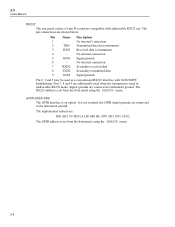
... REMOTE menu. No internal connection 7 RXD2 Secondary received data 8 TXD2 Secondary transmitted data 9 GND Signal ground Pin 2, 3 and 5 may be used in addressable RS232 mode. 271 Users Manual RS232 The rear panel carries a 9-pin D-connector compatible with XON/XOFF handshaking. GPIB (IEEE-488) The GPIB interface is not isolated; the GPIB signal grounds...
... REMOTE menu. No internal connection 7 RXD2 Secondary received data 8 TXD2 Secondary transmitted data 9 GND Signal ground Pin 2, 3 and 5 may be used in addressable RS232 mode. 271 Users Manual RS232 The rear panel carries a 9-pin D-connector compatible with XON/XOFF handshaking. GPIB (IEEE-488) The GPIB interface is not isolated; the GPIB signal grounds...

User Manual
Page 30
... amplitude values. This is not a problem with waveforms; if an error is varied, i.e. how the frequency is changed . However with high resolution from fewer samples. 271 Users Manual Introduction This section is a general introduction to the features and organization of one clock edge sets a practical limit to the upper frequency. it is normally... generator, and is stored in the specification; On this rate is encountered the message "SYSTEM RAM ERROR, 4-2 DDS Principles Waveforms are changed , are , by the user) to be read before using the instrument for the first time.
... amplitude values. This is not a problem with waveforms; if an error is varied, i.e. how the frequency is changed . However with high resolution from fewer samples. 271 Users Manual Introduction This section is a general introduction to the features and organization of one clock edge sets a practical limit to the upper frequency. it is normally... generator, and is stored in the specification; On this rate is encountered the message "SYSTEM RAM ERROR, 4-2 DDS Principles Waveforms are changed , are , by the user) to be read before using the instrument for the first time.

User Manual
Page 32
... keys. the step size is also used , together with fixed units (e.g. When the edit cursor is pressed but ENTER can be stepped into that field. 271 Users Manual Numeric entries are automatically confirmed when the appropriate unit key (Hz, kHz, MHz, etc.) is positioned in a parameter selection field (for example, SOURCE = on the...
... keys. the step size is also used , together with fixed units (e.g. When the edit cursor is pressed but ENTER can be stepped into that field. 271 Users Manual Numeric entries are automatically confirmed when the appropriate unit key (Hz, kHz, MHz, etc.) is positioned in a parameter selection field (for example, SOURCE = on the...

User Manual
Page 34
271 Users Manual 4-6
271 Users Manual 4-6

User Manual
Page 36
... of a period entry is always zero. When an entry is made in terms of period the synthesized frequency is not already in terms of a period; 271 Users Manual Introduction When first switched on, and at all subsequent power-ups unless specified otherwise on the first line of the main menu the frequency can...
... of a period entry is always zero. When an entry is made in terms of period the synthesized frequency is not already in terms of a period; 271 Users Manual Introduction When first switched on, and at all subsequent power-ups unless specified otherwise on the first line of the main menu the frequency can...

User Manual
Page 38
... cursor to this is maintained correctly as a signal invert key. mV with the impedance. alternative presses toggle the sign between 50Ω and 600Ω. 271 Users Manual output level entry and not as a command to toggle between + and -. key to zero, the increment size is in dBm will decrement the offset in...
... cursor to this is maintained correctly as a signal invert key. mV with the impedance. alternative presses toggle the sign between 50Ω and 600Ω. 271 Users Manual output level entry and not as a command to toggle between + and -. key to zero, the increment size is in dBm will decrement the offset in...

User Manual
Page 40
... 80 % as shown in the bracketed field beside the setting. turning the rotary control will be displayed. The offset change which the user might not necessarily expect. The setting will be accepted but the actual symmetry will now be accepted; The error message FREQUENCY/PERIOD VAL ... the frequency below ). Entering a VhiZ of values permitted. If this case the entry is rejected and the parameter setting is left unchanged. 271 Users Manual For example, in the display below the frequency is set to 250 mV p-p brings in the step attenuator; Should the symmetry be limited ...
... 80 % as shown in the bracketed field beside the setting. turning the rotary control will be displayed. The offset change which the user might not necessarily expect. The setting will be accepted but the actual symmetry will now be accepted; The error message FREQUENCY/PERIOD VAL ... the frequency below ). Entering a VhiZ of values permitted. If this case the entry is rejected and the parameter setting is left unchanged. 271 Users Manual For example, in the display below the frequency is set to 250 mV p-p brings in the step attenuator; Should the symmetry be limited ...
