Fluke 271-U Support and Manuals
Get Help and Manuals for this Fluke item

Popular Fluke 271-U Manual Pages
User Manual - Page 1

®
271
Programmable 10 MHz DDS Function Generator
Users Manual
January 2005
© 2005 Fluke Corporation, All rights reserved. Printed in USA All product names are trademarks of their respective companies.
User Manual - Page 2

... warranty may not apply to every buyer. Fluke's warranty obligation is limited, at Fluke's option, to refund of the purchase price, free of charge repair, or replacement of a defective product which , in another country. 271
Users Manual
LIMITED WARRANTY AND LIMITATION OF LIABILITY
Each Fluke product is returned to a Fluke authorized service center within the warranty period. Box 1186...
User Manual - Page 4
...Fluke Service Center for non-volatile memory battery back-up. Caution Do not wet the instrument when cleaning it and in this manual: Caution - Mains supply OFF. Alternating current. In the event of replacement becoming necessary, replace...button cell type 2032.
Typical battery life is 5 years. ii 271
Users Manual
Note This instrument uses a Lithium button cell for recycling information. ...
User Manual - Page 6

Refer to the Service Manual. 271
Users Manual
b) after opening the case for any reason ensure that all case screws are remade correctly before replacing the cover. c) In the event of part replacement becoming necessary, only use components of an identical type.
iv Always ensure all signal and ground connections are correctly refitted and tightened.
User Manual - Page 8

271
Users Manual
General ...1-8
2
Installation 2-1
Mains Operating Voltage 2-2 Fuse...2-2 Mains Lead ...2-2 Mounting...2-2
3
Connections 3-1
Front Panel ... Output Level 5-3 Output Impedance 5-4 DC Offset ...5-4 DC Output ...5-5 Symmetry ...5-5 Warning and Error Messages 5-6 The Auxiliary Output 5-7 Auxiliary Output Phase 5-8 Waveform Generation Options 5-9 Square Wave Generation...
User Manual - Page 10
271
Users Manual
Introduction...13-2 Synchronizing Principles 13-2 Connections for Synchronization 13-2 Generator Set-Ups 13-2 Synchronizing ...13-3
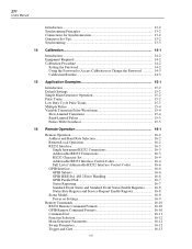
14 Calibration 14-1
Introduction...14-2 Equipment Required 14-2 Calibration Procedure 14-2
Setting the Password 14-2 Using the Password to Access Calibration or Change the Password 14-3 Calibration Routine 14-3
15 Application Examples 15-1
...
User Manual - Page 18

... Carrier waveforms: Switch repetition rate: Switching signal source:
From 0.1 mHz to 1 MHz external. 271
Users Manual
Trigger and burst
Phase-coherent signal keying: each positive edge of the trigger signal will produce one... of the carrier, starting and stopping at the rear panel socket. Start and stop phase setting. See VCA In below. dc to 50 kHz internal, dc to 10 MHz.
All ...
User Manual - Page 20

...by rotary control. operating: +5 to 1 MHz. 271
Users Manual
Inputs
Ext Trig Frequency range: Signal range: Minimum ...176;C Indoor use at maximum output. Keyboard selection of mode, waveform etc.
Installation category II. half-rack (212mm) wide; 330mm deep. 4.1 kg (9 lb....1 and IEEE488.2
General Display: Data Entry: Stored Settings: Size:
Weight: Power:
Temperature range: Environmental:
...
User Manual - Page 24
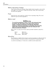
... the set operating voltage. The correct mains fuse types are listed in a 19 inch rack is available from the manufacturers.
2-2 When a three core mains lead with feet for mounting in Appendix A. Brown
Mains Live
Blue
Mains Neutral
Green / Yellow Mains Earth
Mounting
This instrument is suitable both for optimal panel angle. 271
Users Manual...
User Manual - Page 26
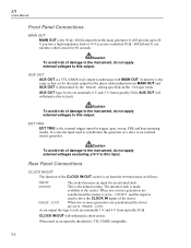
...more generators are nominally 1 V and 4 V from typically 50 Ω.
AUX OUT logic levels are set from the main generator. It is also the input used as an input the threshold is TTL/CMOS ...is
used to this output. EXT TRIG EXT TRIG is the default setting.
AUX OUT will withstand a short-circuit.
271
Users Manual
Front Panel Connections
MAIN OUT MAIN OUT is the 50 Ω /...
User Manual - Page 28
... are additionally used when the instrument is set from instrument
3
RXD Received data to instrument
4
-
Pins 7, 8 and 9 are connected to instrument ground. GPIB (IEEE-488) The GPIB interface is not isolated;
No internal Connection
2
TXD Transmitted data from the front panel using the REMOTE menu.
3-4 271
Users Manual
RS232
The rear panel carries a 9-pin...
User Manual - Page 30

...specification; However with sine waves which reconstructs the waveform. 271
Users Manual...user) to make every parameter programmable from fewer samples.
Sine waves and triangles are , by direct digital synthesis (DDS).
if an error is not a problem with DDS square waves and pulse waveforms the uncertainty of one clock edge sets...generator displays the installed software revision whilst...
User Manual - Page 34

271
Users Manual
4-6
User Manual - Page 114
A-2
271
Users Manual
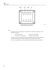
Mains transformer connections
sha0021f.emf
Fuse
Ensure that the correct mains fuse is prohibited. The use of makeshift fuses or the short-circuiting of the fuse holder is fitted for 100V or 115V operation:
250 mA (T) 250 V HRC 500 mA (T) 250 V HRC
To replace the fuse, disconnect the mains lead from the inlet...
Getting Started Guide - Page 16
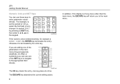
.... otherwise it to period (PER) by the units key.
shx0009f.gif
If the numeric value is of the SET keys to navigate to the appropriate field directly.
If you are editing one of the parameters in the main menu...will return you can use one key press at a time. 271 Getting Started Manual
Numeric, Units and SET Keys
You can use these keys to enter parameter values directly.
Fluke 271-U Reviews
We have not received any reviews for Fluke yet.