

User Manual
Page 2
... on non-defective media. Warranty support is available only if product is purchased through a Fluke authorized sales outlet or Buyer has paid the applicable international price. 271 Users Manual LIMITED WARRANTY AND LIMITATION OF LIABILITY Each Fluke product is warranted to be error free or operate without interruption. Fluke does not warrant that software will be billed for 90 days. FLUKE SHALL NOT BE LIABLE FOR...
... on non-defective media. Warranty support is available only if product is purchased through a Fluke authorized sales outlet or Buyer has paid the applicable international price. 271 Users Manual LIMITED WARRANTY AND LIMITATION OF LIABILITY Each Fluke product is warranted to be error free or operate without interruption. Fluke does not warrant that software will be billed for 90 days. FLUKE SHALL NOT BE LIABLE FOR...

User Manual
Page 3
.... • When the instrument is connected to its rated supply voltages or environmental range. It is prohibited. Use of the specified type are used for Measurement, Control and Laboratory Use). It may impair the safety protection provided. The use of an extension cord without degradation of EN61010-1 (Safety Requirements for Electrical Equipment for replacement. This instruction manual contains some information and warnings which access can...
.... • When the instrument is connected to its rated supply voltages or environmental range. It is prohibited. Use of the specified type are used for Measurement, Control and Laboratory Use). It may impair the safety protection provided. The use of an extension cord without degradation of EN61010-1 (Safety Requirements for Electrical Equipment for replacement. This instruction manual contains some information and warnings which access can...
User Manual
Page 4
... it and in this manual: Caution - Terminal connected to recharge. 271 Users Manual Note This instrument uses a Lithium button cell for recycling information. Alternating current. Used batteries should be present. Mains supply ON. hazardous voltages may damage the instrument. Do not cut open, incinerate, expose to temperatures above 60 °C or attempt to chassis ground. The following symbols are used on the instrument...
... it and in this manual: Caution - Terminal connected to recharge. 271 Users Manual Note This instrument uses a Lithium button cell for recycling information. Alternating current. Used batteries should be present. Mains supply ON. hazardous voltages may damage the instrument. Do not cut open, incinerate, expose to temperatures above 60 °C or attempt to chassis ground. The following symbols are used on the instrument...

User Manual
Page 5
...-4-2 (1995) Electrostatic Discharge: 4 kV air, 4 kV contact Performance A. Immunity EN61326 (1998) EMC product standard for Electrical Equipment for Measurement, Control and Laboratory Use. Test limits used were: a) Radiated: Class B b) Conducted...Voltage Interrupt: 1 cycle, 100 % Performance A. signal connections EMC Compliance This instrument meets the requirements of the following standards: Emissions EN61326 (1998) EMC product standard for Electrical Equipment for Measurement, Control and Laboratory Use. e) EN61000-4-5 (1995) Surge: 0.5 kV (line to line), 1 kV (line to ground...
...-4-2 (1995) Electrostatic Discharge: 4 kV air, 4 kV contact Performance A. Immunity EN61326 (1998) EMC product standard for Electrical Equipment for Measurement, Control and Laboratory Use. Test limits used were: a) Radiated: Class B b) Conducted...Voltage Interrupt: 1 cycle, 100 % Performance A. signal connections EMC Compliance This instrument meets the requirements of the following standards: Emissions EN61326 (1998) EMC product standard for Electrical Equipment for Measurement, Control and Laboratory Use. e) EN61000-4-5 (1995) Surge: 0.5 kV (line to line), 1 kV (line to ground...

User Manual
Page 6
Always ensure all signal and ground connections are correctly refitted and tightened. c) In the event of part replacement becoming necessary, only use components of an identical type. Refer to the Service Manual. iv 271 Users Manual b) after opening the case for any reason ensure that all case screws are remade correctly before replacing the cover.
Always ensure all signal and ground connections are correctly refitted and tightened. c) In the event of part replacement becoming necessary, only use components of an identical type. Refer to the Service Manual. iv 271 Users Manual b) after opening the case for any reason ensure that all case screws are remade correctly before replacing the cover.
User Manual
Page 10
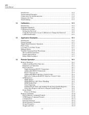
271 Users Manual Introduction...13-2 Synchronizing Principles 13-2 Connections for Synchronization 13-2 Generator Set-Ups 13-2 Synchronizing ...13-3 14 Calibration 14-1 Introduction...14-2 Equipment Required 14-2 Calibration Procedure 14-2 Setting the Password 14-2 Using the Password to Access Calibration or Change the Password 14-3 Calibration Routine 14-3 15 Application Examples 15-1 Introduction...15-2 Default Settings 15-2 Simple Main Generator Operation 15-2 Pulse Trains...15-2 Low Duty Cycle Pulse...
271 Users Manual Introduction...13-2 Synchronizing Principles 13-2 Connections for Synchronization 13-2 Generator Set-Ups 13-2 Synchronizing ...13-3 14 Calibration 14-1 Introduction...14-2 Equipment Required 14-2 Calibration Procedure 14-2 Setting the Password 14-2 Using the Password to Access Calibration or Change the Password 14-3 Calibration Routine 14-3 15 Application Examples 15-1 Introduction...15-2 Default Settings 15-2 Simple Main Generator Operation 15-2 Pulse Trains...15-2 Low Duty Cycle Pulse...

User Manual
Page 14
...Sweeps are related to that of the crystal master clock. In addition the DDS generator offers high spectral purity, low phase noise and excellent frequency agility. In ...controlled by the switching signal source. 1-2 Modulation may also be triggered from the front panel, the trigger input or the digital interfaces. Two sweep markers are pre-defined in 1 % steps up table and a DAC. A wide range of 0.1 mHz to 10 MHz. 271 Users Manual Introduction This Programmable Function Generator uses direct digital synthesis to provide high performance and extensive facilities at a rate...
...Sweeps are related to that of the crystal master clock. In addition the DDS generator offers high spectral purity, low phase noise and excellent frequency agility. In ...controlled by the switching signal source. 1-2 Modulation may also be triggered from the front panel, the trigger input or the digital interfaces. Two sweep markers are pre-defined in 1 % steps up table and a DAC. A wide range of 0.1 mHz to 10 MHz. 271 Users Manual Introduction This Programmable Function Generator uses direct digital synthesis to provide high performance and extensive facilities at a rate...

User Manual
Page 15
...) with 4 rows of the carrier, starting and stopping at a predetermined rate or in the burst can be set up to phase lock two or more generators. Duration is low. Phase locked generators can be defined in addressable mode whereby up to 1 MHz externally. 1 Introduction and Specifications Introduction The rate can be operated from the internal trigger generator (0.005 Hz to 50 kHz...
...) with 4 rows of the carrier, starting and stopping at a predetermined rate or in the burst can be set up to phase lock two or more generators. Duration is low. Phase locked generators can be defined in addressable mode whereby up to 1 MHz externally. 1 Introduction and Specifications Introduction The rate can be operated from the internal trigger generator (0.005 Hz to 50 kHz...

User Manual
Page 20
...Data Entry: Stored Settings: Size: Weight: Power: Temperature range: Environmental: 20 character x 4 row alphanumeric LCD. Up to +60 °C Indoor use at maximum output. Output logic levels nominally 1 V and 4 V from battery-backed memory. 3U (130mm) high; operating: +5 to 1 MHz. storage: -20 to 9 complete instrument set-ups may be addressed from one RS232 port... 100 kHz. 2.5 V for 100% level change at altitudes up to 2000 m, 1-8 Value entry direct by numeric keys or by rotary control. Installation category II. 271 Users Manual Inputs Ext Trig Frequency range: Signal range: ...
...Data Entry: Stored Settings: Size: Weight: Power: Temperature range: Environmental: 20 character x 4 row alphanumeric LCD. Up to +60 °C Indoor use at maximum output. Output logic levels nominally 1 V and 4 V from battery-backed memory. 3U (130mm) high; operating: +5 to 1 MHz. storage: -20 to 9 complete instrument set-ups may be addressed from one RS232 port... 100 kHz. 2.5 V for 100% level change at altitudes up to 2000 m, 1-8 Value entry direct by numeric keys or by rotary control. Installation category II. 271 Users Manual Inputs Ext Trig Frequency range: Signal range: ...
User Manual
Page 24
... mounting. A rack kit for mounting in a 19 inch rack is necessary to change the operating voltage, follow the procedure described in Appendix A. If it should be connected as follows:- The correct mains fuse types are listed in the appendix. The protective action must be negated by the use and rack mounting. 271 Users Manual Mains Operating Voltage Check that the correct mains fuse is fitted for the set operating voltage...
... mounting. A rack kit for mounting in a 19 inch rack is necessary to change the operating voltage, follow the procedure described in Appendix A. If it should be connected as follows:- The correct mains fuse types are listed in the appendix. The protective action must be negated by the use and rack mounting. 271 Users Manual Mains Operating Voltage Check that the correct mains fuse is fitted for the set operating voltage...
User Manual
Page 26
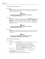
... an external master generator. Symmetry is the same as a slave to 20 V p-p into a high-impedance load or 10 V p-p into a matched 50 Ω / 600 Ω load. The internal clock is set from the main generator. CLOCK IN/OUT will withstand a short-circuit. 271 Users Manual Front Panel Connections MAIN OUT MAIN OUT is the 50 Ω / 600 Ω output from the SYStem menu...
... an external master generator. Symmetry is the same as a slave to 20 V p-p into a high-impedance load or 10 V p-p into a matched 50 Ω / 600 Ω load. The internal clock is set from the main generator. CLOCK IN/OUT will withstand a short-circuit. 271 Users Manual Front Panel Connections MAIN OUT MAIN OUT is the 50 Ω / 600 Ω output from the SYStem menu...

User Manual
Page 27
... internal trigger generator, a fixed amplitude square wave whose frequency is a 3-level waveform, changing from typically 50 Ω. Output levels are nominally 0 V and 5 V from high (4 V) to low (0 V) at start of damage to the instrument, do not apply external voltages exceeding ±10 V to this output is that step have been set on the master generator is connected to each marker point. SYNC OUT...
... internal trigger generator, a fixed amplitude square wave whose frequency is a 3-level waveform, changing from typically 50 Ω. Output levels are nominally 0 V and 5 V from high (4 V) to low (0 V) at start of damage to the instrument, do not apply external voltages exceeding ±10 V to this output is that step have been set on the master generator is connected to each marker point. SYNC OUT...

User Manual
Page 30
... waveforms are sampled. 271 Users Manual Introduction This section is a general introduction to the features and organization of the generator. Further details of one clock edge sets a practical limit to the upper frequency. The major advantages of the front panel. Very wide frequency sweeps are : 1. Switching On The power switch is located at higher frequencies the addresses are , however, available...
... waveforms are sampled. 271 Users Manual Introduction This section is a general introduction to the features and organization of the generator. Further details of one clock edge sets a practical limit to the upper frequency. The major advantages of the front panel. Very wide frequency sweeps are : 1. Switching On The power switch is located at higher frequencies the addresses are , however, available...

User Manual
Page 31
... the SET keys) for manual triggering and synchronizing two or more fully below under Principles of ambient temperature or viewing angle but can be displayed. Lastly, the ENTER, ESCAPE, and CE (Clear Entry) keys have self-explanatory functions. 4-3 Pressing a different key selects the function last selected with changes of Editing. 5. the MAN/SYNC key is explained more generators...
... the SET keys) for manual triggering and synchronizing two or more fully below under Principles of ambient temperature or viewing angle but can be displayed. Lastly, the ENTER, ESCAPE, and CE (Clear Entry) keys have self-explanatory functions. 4-3 Pressing a different key selects the function last selected with changes of Editing. 5. the MAN/SYNC key is explained more generators...

User Manual
Page 48
... Principles of a circuit. Connections for use of sweep with an oscilloscope or hard-copy device to 1010:1. Additionally the TRIG/SWEEP OUT output provides narrow 1 V pulses at the front panel EXT TRIG socket. The generator does not provide a ramp output for Sweep Operation Sweeps are set to an oscilloscope or, for additional information. 271 Users Manual Introduction DDS operation gives the...
... Principles of a circuit. Connections for use of sweep with an oscilloscope or hard-copy device to 1010:1. Additionally the TRIG/SWEEP OUT output provides narrow 1 V pulses at the front panel EXT TRIG socket. The generator does not provide a ramp output for Sweep Operation Sweeps are set to an oscilloscope or, for additional information. 271 Users Manual Introduction DDS operation gives the...

User Manual
Page 86
... circumstances the simplest means of restoring operation is not lit, press OUTPUT to work through the examples connect MAIN OUT from the keyboard. Select SINE on an oscilloscope. 271 Users Manual Introduction Some examples of the many ways of configuring the waveform, trigger or modulation settings which are given in turn using the FIELD keys. Using the keyboard enter 1, 0, V to restore the...
... circumstances the simplest means of restoring operation is not lit, press OUTPUT to work through the examples connect MAIN OUT from the keyboard. Select SINE on an oscilloscope. 271 Users Manual Introduction Some examples of the many ways of configuring the waveform, trigger or modulation settings which are given in turn using the FIELD keys. Using the keyboard enter 1, 0, V to restore the...

User Manual
Page 113
... use, check that the instrument operating voltage marked on the rear panel must be necessary to change the operating voltage, proceed as follows: for 230V operation connect the live (brown) wire to pin 15 for 115V operation connect the live (brown) wire to pin 14 for the local supply. Should it be changed to clearly show the new voltage setting. Warning To avoid the possibility of the correct rating...
... use, check that the instrument operating voltage marked on the rear panel must be necessary to change the operating voltage, proceed as follows: for 230V operation connect the live (brown) wire to pin 15 for 115V operation connect the live (brown) wire to pin 14 for the local supply. Should it be changed to clearly show the new voltage setting. Warning To avoid the possibility of the correct rating...

Getting Started Guide
Page 2
... prepaid (FOB Destination). Fluke does not warrant that service center, with its functional specifications for repair in one year and begins on behalf of repair/replacement parts when product purchased in another country. Warranty support is available only if product is warranted to every buyer. LIMITED WARRANTY AND LIMITATION OF LIABILITY Each Fluke product is purchased through a Fluke authorized sales outlet or Buyer has...
... prepaid (FOB Destination). Fluke does not warrant that service center, with its functional specifications for repair in one year and begins on behalf of repair/replacement parts when product purchased in another country. Warranty support is available only if product is warranted to every buyer. LIMITED WARRANTY AND LIMITATION OF LIABILITY Each Fluke product is purchased through a Fluke authorized sales outlet or Buyer has...
Getting Started Guide
Page 16
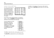
...you are editing one of any menu other than the main menu, the ESCAPE key will return you can use one key press at a time. 271 Getting Started Manual Numeric, Units and SET Keys You can use these keys to period (PER) by the units key. The ESCAPE key abandons the current editing action. 6... directly. shx0009f.gif If the numeric value is terminated by pressing a DIGIT key, then enter 1, 2, 5, us on the keypad. For example, to set the period to 125 µs, select the first field (FREQ), change it is dimensionless, for example a BURST COUNT, the ENTER key terminates the entry;
...you are editing one of any menu other than the main menu, the ESCAPE key will return you can use one key press at a time. 271 Getting Started Manual Numeric, Units and SET Keys You can use these keys to period (PER) by the units key. The ESCAPE key abandons the current editing action. 6... directly. shx0009f.gif If the numeric value is terminated by pressing a DIGIT key, then enter 1, 2, 5, us on the keypad. For example, to set the period to 125 µs, select the first field (FREQ), change it is dimensionless, for example a BURST COUNT, the ENTER key terminates the entry;

Getting Started Guide
Page 29
... internal trigger generator. outside this , 15.625 kHz. First, free the internal trigger generator. These levels usually correspond to the factory default settings. Getting Started Using the Instrument Special Waveforms Staircases The instrument can also be driven from 12.05 to start the generator with up process we will create a signal that approximates a 625-line PAL TV line signal. the following settings give...
... internal trigger generator. outside this , 15.625 kHz. First, free the internal trigger generator. These levels usually correspond to the factory default settings. Getting Started Using the Instrument Special Waveforms Staircases The instrument can also be driven from 12.05 to start the generator with up process we will create a signal that approximates a 625-line PAL TV line signal. the following settings give...


