Fluke ScopeMeter Product Datasheet
Page 2
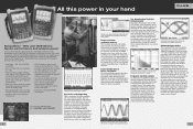
...screen color labels, measurements and warnings are clearly linked to specific waveforms. See dynamic signal behavior instantaneously The Digital Persistence mode (Fluke 190C) helps to 2.5 GS/s real-time sampling per input record length using FlukeView® ScopeMeter software. A fully isolated external... simplifies triggering with 400 ps resolution. The spectrum analysis function is included for analyz- And thanks to help you may manually select your hand ScopeMeter® 190C and 190B Series: Speed, performance and analysis power For the more demanding applications,...
...screen color labels, measurements and warnings are clearly linked to specific waveforms. See dynamic signal behavior instantaneously The Digital Persistence mode (Fluke 190C) helps to 2.5 GS/s real-time sampling per input record length using FlukeView® ScopeMeter software. A fully isolated external... simplifies triggering with 400 ps resolution. The spectrum analysis function is included for analyz- And thanks to help you may manually select your hand ScopeMeter® 190C and 190B Series: Speed, performance and analysis power For the more demanding applications,...

FE 123 & 124 Users Manual
Page 1
® Fluke 123/124 Industrial ScopeMeter GB Sep 2002 © 2002 Fluke Corporation. All rights reserved. All product names are trademarks of their respective companies. Users Manual
® Fluke 123/124 Industrial ScopeMeter GB Sep 2002 © 2002 Fluke Corporation. All rights reserved. All product names are trademarks of their respective companies. Users Manual
FE 123 & 124 Users Manual
Page 6
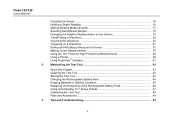
Fluke 123/124 Users Manual Freezing the Screen...16 Holding a Stable Reading 16 Making Relative Measurements 17 Selecting Auto/Manual Ranges 18 Changing the Graphic Representation on the Screen 18 TrendPlotting a Waveform 22 Acquiring the Waveform 23 Triggering on a Waveform 27 Saving and Recalling a Setup ...
Fluke 123/124 Users Manual Freezing the Screen...16 Holding a Stable Reading 16 Making Relative Measurements 17 Selecting Auto/Manual Ranges 18 Changing the Graphic Representation on the Screen 18 TrendPlotting a Waveform 22 Acquiring the Waveform 23 Triggering on a Waveform 27 Saving and Recalling a Setup ...

FE 123 & 124 Users Manual
Page 8
Fluke 123/124 Users Manual iv
Fluke 123/124 Users Manual iv
FE 123 & 124 Users Manual
Page 10
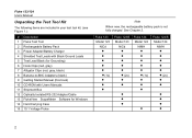
.../S Model 123 NiCd 2x) • • • • • Fluke 124 Model 124 NiMH 1x • Fluke 124/S Model 124 NiMH 2x) • • 2 Fluke 123/124 Users Manual Unpacking the Test Tool Kit The following items are included in your test tool kit. (see Figure 1.): # Description 1 Fluke Test Tool 2 Rechargeable Battery Pack 3 Power Adapter/Battery Charger 4 Shielded Test Leads...
.../S Model 123 NiCd 2x) • • • • • Fluke 124 Model 124 NiMH 1x • Fluke 124/S Model 124 NiMH 2x) • • 2 Fluke 123/124 Users Manual Unpacking the Test Tool Kit The following items are included in your test tool kit. (see Figure 1.): # Description 1 Fluke Test Tool 2 Rechargeable Battery Pack 3 Power Adapter/Battery Charger 4 Shielded Test Leads...
FE 123 & 124 Users Manual
Page 12
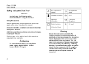
...peak (30V rms), not being detected. Warning To avoid electrical shock, use only Fluke power supply, Model PM8907 (Power Adapter/Battery Charger). 4 See explanation in manual Disposal information Equal potential inputs Earth Recycling information Double Insulation (Protection Class) Conformité... Européenne UL listed Warning Should this manual are explained in fully automatic mode. Fluke 123/124 Users Manual Safely Using the Test Tool Attention Carefully read the following safety information before using the test ...
...peak (30V rms), not being detected. Warning To avoid electrical shock, use only Fluke power supply, Model PM8907 (Power Adapter/Battery Charger). 4 See explanation in manual Disposal information Equal potential inputs Earth Recycling information Double Insulation (Protection Class) Conformité... Européenne UL listed Warning Should this manual are explained in fully automatic mode. Fluke 123/124 Users Manual Safely Using the Test Tool Attention Carefully read the following safety information before using the test ...
FE 123 & 124 Users Manual
Page 14
...equipment. The isolated input connectors have no exposed metal and are fully insulated to ground 600 V CAT III Voltage ratings are used in this manual to indicate a measurement in the manner specified. Whenever it is likely that safety has been impaired, the Test Tool must be read as... Input A and B directly 600 V CAT III Input A and B via BB120 300 V CAT III Input A and B via STL120 600 V CAT III Max. Fluke 123/124 Users Manual • Do not insert metal objects into connectors. • Always use , inspect the test leads for mechanical damage and replace damaged test leads! The...
...equipment. The isolated input connectors have no exposed metal and are fully insulated to ground 600 V CAT III Voltage ratings are used in this manual to indicate a measurement in the manner specified. Whenever it is likely that safety has been impaired, the Test Tool must be read as... Input A and B directly 600 V CAT III Input A and B via BB120 300 V CAT III Input A and B via STL120 600 V CAT III Max. Fluke 123/124 Users Manual • Do not insert metal objects into connectors. • Always use , inspect the test leads for mechanical damage and replace damaged test leads! The...
FE 123 & 124 Users Manual
Page 16
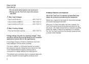
in Fluke 124 this key is used to restore the test tool settings as delivered from the factory, do the following: Turn the test tool off. Release. Press and release. you want to switch the cursors on , and you should hear a double beep, indicating the Reset was successful. Press and hold. Now look at the display; Fluke 123 Fluke 124 Figure 1-2. Fluke 123/124 Users Manual Resetting the Test Tool If you will see a screen that looks like Figure 1-2. The test tool turns on . The Screen After Reset 8 The F4 key of Fluke 123 is used to control the contrast;
in Fluke 124 this key is used to restore the test tool settings as delivered from the factory, do the following: Turn the test tool off. Release. Press and release. you want to switch the cursors on , and you should hear a double beep, indicating the Reset was successful. Press and hold. Now look at the display; Fluke 123 Fluke 124 Figure 1-2. Fluke 123/124 Users Manual Resetting the Test Tool If you will see a screen that looks like Figure 1-2. The test tool turns on . The Screen After Reset 8 The F4 key of Fluke 123 is used to control the contrast;
FE 123 & 124 Users Manual
Page 18
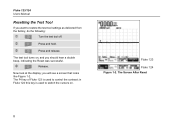
... with choices accessed with the arrow keys: . 10 Fluke 123 Fluke 124 Figure 1-3. The Screen Area's Note When battery powered, the battery indicator informs you change a setup, a part of the battery from full to display the choices. Refer to Figure 1-3 during the following. Fluke 123/124 Users Manual Reading the Screen The screen is used to...
... with choices accessed with the arrow keys: . 10 Fluke 123 Fluke 124 Figure 1-3. The Screen Area's Note When battery powered, the battery indicator informs you change a setup, a part of the battery from full to display the choices. Refer to Figure 1-3 during the following. Fluke 123/124 Users Manual Reading the Screen The screen is used to...

FE 123 & 124 Users Manual
Page 20
Input B For measurements on two different signals you can use the red input A for Continuity, Ohm (Ω), Diode, and Capacitance measurements. Measurement Connections Fluke 123/124 Users Manual Looking at the Measurement Connections Look at the same potential. 12 Figure 1-5. COM You can always use the gray input B together with the test tool. ...
Input B For measurements on two different signals you can use the red input A for Continuity, Ohm (Ω), Diode, and Capacitance measurements. Measurement Connections Fluke 123/124 Users Manual Looking at the Measurement Connections Look at the same potential. 12 Figure 1-5. COM You can always use the gray input B together with the test tool. ...
FE 123 & 124 Users Manual
Page 22
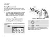
Select Hz. The former main reading has now moved to be measured. Fluke 123/124 Users Manual Making Measurements The reading area displays the numeric readings of the chosen measurements on the waveform that Hz is applied to the input jack. • ...
Select Hz. The former main reading has now moved to be measured. Fluke 123/124 Users Manual Making Measurements The reading area displays the numeric readings of the chosen measurements on the waveform that Hz is applied to the input jack. • ...

FE 123 & 124 Users Manual
Page 24
... any time. Return to update with valid readings (and beeps) as longs as you have a stable display. Use the following procedure for hands-free measurements. Fluke 123/124 Users Manual Freezing the Screen You can use this function for the Touch Hold function: Open the INPUT A menu. Freeze the screen.
... any time. Return to update with valid readings (and beeps) as longs as you have a stable display. Use the following procedure for hands-free measurements. Fluke 123/124 Users Manual Freezing the Screen You can use this function for the Touch Hold function: Open the INPUT A menu. Freeze the screen.
FE 123 & 124 Users Manual
Page 26
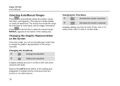
...Fluke 124) to change the graphic representation on nearly all waveforms. The bottom line shows the range, the time base for both inputs, and the trigger information. Reduce the waveform. Decrease the number of periods. MANUAL appears at the bottom of the reading area disappears to select the manual range. Fluke 123/124 Users Manual Selecting Auto/Manual... Ranges Press to 500 V/div when using the test leads. This assures a stable display on the screen manually. Changing the Amplitude ...
...Fluke 124) to change the graphic representation on nearly all waveforms. The bottom line shows the range, the time base for both inputs, and the trigger information. Reduce the waveform. Decrease the number of periods. MANUAL appears at the bottom of the reading area disappears to select the manual range. Fluke 123/124 Users Manual Selecting Auto/Manual... Ranges Press to 500 V/div when using the test leads. This assures a stable display on the screen manually. Changing the Amplitude ...

FE 123 & 124 Users Manual
Page 28
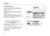
Fluke 123/124 Users Manual Smoothing the Waveform To smooth the waveform, do the following: Open the SCOPE INPUTS menu. Highlight SMOOTH. You can use waveform smooth to WAVEFORM MODE. Open the SCOPE OPTIONS submenu. Waveform samples with and without loss of bandwidth. Jump to suppress noise without smoothing are shown in Figure 1-11. 20 Figure 1-11. Accept waveform smooth. Smoothing the Waveform
Fluke 123/124 Users Manual Smoothing the Waveform To smooth the waveform, do the following: Open the SCOPE INPUTS menu. Highlight SMOOTH. You can use waveform smooth to WAVEFORM MODE. Open the SCOPE OPTIONS submenu. Waveform samples with and without loss of bandwidth. Jump to suppress noise without smoothing are shown in Figure 1-11. 20 Figure 1-11. Accept waveform smooth. Smoothing the Waveform
FE 123 & 124 Users Manual
Page 30
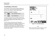
... occurs and the new minimum is full. The TrendPlot is built up on the screen. Date and time stamp shows the time of input A. Fluke 123/124 Users Manual TrendPlotting a Waveform The TrendPlot™ function plots the digital readings as graphs. Automatic vertical scaling and horizontal time compression resizes the TrendPlot to fit...
... occurs and the new minimum is full. The TrendPlot is built up on the screen. Date and time stamp shows the time of input A. Fluke 123/124 Users Manual TrendPlotting a Waveform The TrendPlot™ function plots the digital readings as graphs. Automatic vertical scaling and horizontal time compression resizes the TrendPlot to fit...

FE 123 & 124 Users Manual
Page 32
Making a Single Acquisition 24 To perform a next single acquisition, do the following: Wait for a trigger. Figure 1-14. The test tool will now have a screen like Figure 1-14. Fluke 123/124 Users Manual Wait appears on bottom of the screen to indicate that the test tool is triggered. Hold appears on bottom of the screen when the single acquisition has been completed. Run appears on bottom of the screen when the single acquisition is waiting for another single acquisition trigger.
Making a Single Acquisition 24 To perform a next single acquisition, do the following: Wait for a trigger. Figure 1-14. The test tool will now have a screen like Figure 1-14. Fluke 123/124 Users Manual Wait appears on bottom of the screen to indicate that the test tool is triggered. Hold appears on bottom of the screen when the single acquisition has been completed. Run appears on bottom of the screen when the single acquisition is waiting for another single acquisition trigger.

FE 123 & 124 Users Manual
Page 34
... inverted waveform display. Open the SCOPE INPUTS menu. Reversing the Polarity of INPUT A). For example, a negative-going , providing a more meaningful viewing perspective in some cases. Fluke 123/124 Users Manual Selecting AC-Coupling Use AC-coupling when you wish to observe a small AC signal that rides on left of the waveform area. 26
... inverted waveform display. Open the SCOPE INPUTS menu. Reversing the Polarity of INPUT A). For example, a negative-going , providing a more meaningful viewing perspective in some cases. Fluke 123/124 Users Manual Selecting AC-Coupling Use AC-coupling when you wish to observe a small AC signal that rides on left of the waveform area. 26

FE 123 & 124 Users Manual
Page 35
... trigger on nearly all Trigger Information 27 Finally you can tell the test tool to begin displaying the waveform. To optimize trigger level and slope manually, do the following: Press until you have left any open menu. Trigger icons on the second time division line indicates the trigger level. Figure 1-16...
... trigger on nearly all Trigger Information 27 Finally you can tell the test tool to begin displaying the waveform. To optimize trigger level and slope manually, do the following: Press until you have left any open menu. Trigger icons on the second time division line indicates the trigger level. Figure 1-16...

FE 123 & 124 Users Manual
Page 36
... 'A'. Highlight >1 Hz 28 Accept all trigger selections and return to >1Hz will slow down the auto range. Note Setting the automatic triggering to normal measurement. Fluke 123/124 Users Manual Selecting the Trigger Parameters To trigger on bottom of the screen when no trigger is not valid.
... 'A'. Highlight >1 Hz 28 Accept all trigger selections and return to >1Hz will slow down the auto range. Note Setting the automatic triggering to normal measurement. Fluke 123/124 Users Manual Selecting the Trigger Parameters To trigger on bottom of the screen when no trigger is not valid.

FE 123 & 124 Users Manual
Page 38
Measuring Video Signals 30 Accept the video trigger selections . Figure 1-18. Trigger level and slope are now fixed. (See Figure 1-18.) Positive video is indicated as a "+" icon on bottom of the screen. Fluke 123/124 Users Manual Highlight POSITIVE.
Measuring Video Signals 30 Accept the video trigger selections . Figure 1-18. Trigger level and slope are now fixed. (See Figure 1-18.) Positive video is indicated as a "+" icon on bottom of the screen. Fluke 123/124 Users Manual Highlight POSITIVE.


