
Installation Manual
Page 6
...to the TM-H6000/TM-U675 15 Attaching to Other TM Printers 20 Attaching to the DM-D stand 23 Part Names and Functions 30 Exterior 30 DIP Switch 31 DIP Switch Functions 31 Turning and Tilting the DM-D210 33 Self Test 34 Check Items of Self test 34 ...Performing Self test 34 Diagnostics 34 Specification 35 General Specifications 35 Electrical Specifications 38 Environmental Specifications 38 Character Specifications 39 Reliability Specification 39 4
...to the TM-H6000/TM-U675 15 Attaching to Other TM Printers 20 Attaching to the DM-D stand 23 Part Names and Functions 30 Exterior 30 DIP Switch 31 DIP Switch Functions 31 Turning and Tilting the DM-D210 33 Self Test 34 Check Items of Self test 34 ...Performing Self test 34 Diagnostics 34 Specification 35 General Specifications 35 Electrical Specifications 38 Environmental Specifications 38 Character Specifications 39 Reliability Specification 39 4
Installation Manual
Page 7
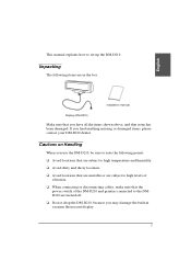
...DM-D210, be sure to the DMD210 are in vacuum fluorescent display. 5 If you may damage the built-in the box. English This manual explains how to high levels of vibration. ❏ When connecting or disconnecting cables, make sure that none has been damaged. installation manual Display (DM-D210)...above, and that the power switch of the DM-D210 and printers connected to note the following items are turned off. ❏ Do not drop the DM-D210, because you find anything missing or damaged items, please contact your DM-D210 dealer. Unpacking The following points: ❏ Avoid...
...DM-D210, be sure to the DMD210 are in vacuum fluorescent display. 5 If you may damage the built-in the box. English This manual explains how to high levels of vibration. ❏ When connecting or disconnecting cables, make sure that none has been damaged. installation manual Display (DM-D210)...above, and that the power switch of the DM-D210 and printers connected to note the following items are turned off. ❏ Do not drop the DM-D210, because you find anything missing or damaged items, please contact your DM-D210 dealer. Unpacking The following points: ❏ Avoid...
Installation Manual
Page 8
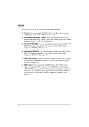
... printers. You can attach the DM-D210 to the TM-U375/ TM-U950 printers using the "DM-D pole unit for TM printers (Type A)" (DP-502). (See page 12.) ❏ TM-H6000/TM-U675. You can attach the DM-D210 to the IR series using the "DM-D pole unit for DM Customer Display" (DP-110). Usage The DM-D210 can attach the DM-D210 using the "DM...
... printers. You can attach the DM-D210 to the TM-U375/ TM-U950 printers using the "DM-D pole unit for TM printers (Type A)" (DP-502). (See page 12.) ❏ TM-H6000/TM-U675. You can attach the DM-D210 to the IR series using the "DM-D pole unit for DM Customer Display" (DP-110). Usage The DM-D210 can attach the DM-D210 using the "DM...
Installation Manual
Page 11
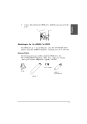
Required items The following items are packed with the "DM-D pole unit for TM printers (Type B)" (DP-503). These items are used to attach the DM-D210 to the TM-H5000II/TM-J8000 printers. base support C fixing screws support B (for TM printers (Type B)" (DP-503). English 5. Connect the cable for the DM-D210 to the TM-H5000II/TM-J8000 printers using the "DM-D pole unit for extension) 9 Attaching to the TM-H5000II/TM-J8000 The DM-D210 can be attached directly to the DM connector on the IR series.
Required items The following items are packed with the "DM-D pole unit for TM printers (Type B)" (DP-503). These items are used to attach the DM-D210 to the TM-H5000II/TM-J8000 printers. base support C fixing screws support B (for TM printers (Type B)" (DP-503). English 5. Connect the cable for the DM-D210 to the TM-H5000II/TM-J8000 printers using the "DM-D pole unit for extension) 9 Attaching to the TM-H5000II/TM-J8000 The DM-D210 can be attached directly to the DM connector on the IR series.
Installation Manual
Page 12
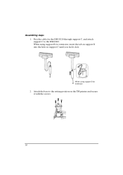
When using support B for extension 2. Attach the base to the DM-D210. When using support B for extension, insert the tab on support B into the hole on the TM printer and secure it click. Assembling steps 1. Pass the cable for the DM-D210 through support C, and attach support C to the setting position on support C until you feel it with the screws. 10
When using support B for extension 2. Attach the base to the DM-D210. When using support B for extension, insert the tab on support B into the hole on the TM printer and secure it click. Assembling steps 1. Pass the cable for the DM-D210 through support C, and attach support C to the setting position on support C until you feel it with the screws. 10
Installation Manual
Page 13
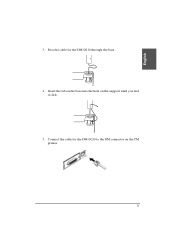
Connect the cable for the DM-D210 through the base. 4. Pass the cable for the DM-D210 to the DM connector on the support until you feel it click. 5. Insert the tab on the base into the hole on the TM printer. 11 English 3.
Connect the cable for the DM-D210 through the base. 4. Pass the cable for the DM-D210 to the DM connector on the support until you feel it click. 5. Insert the tab on the base into the hole on the TM printer. 11 English 3.

Installation Manual
Page 14
...position support C support B for TM printers (Type A)" (DP-502). Required items The following items are packed with the "DM-D pole unit for TM printers (Type A)" (DP-502). These items are used to attach the DM-D210 to the TM-U375/TM-U950 printers using the "DM-D pole unit for extension fixing plate A... 12 Attaching to the TM-U375/TM-U950 The DM-D210 can be attached directly...
...position support C support B for TM printers (Type A)" (DP-502). Required items The following items are packed with the "DM-D pole unit for TM printers (Type A)" (DP-502). These items are used to attach the DM-D210 to the TM-U375/TM-U950 printers using the "DM-D pole unit for extension fixing plate A... 12 Attaching to the TM-U375/TM-U950 The DM-D210 can be attached directly...

Installation Manual
Page 15
When using support B for extension [TM-U375] [TM-U950] 13 English Assembling steps 1. When using support B for the DM-D210 through support C, and attach support C to the printer. Attach the rubber feet to the DM-D210. Pass the cable for extension, insert the tab on support B into the hole on support C until you feel it click. 2.
When using support B for extension [TM-U375] [TM-U950] 13 English Assembling steps 1. When using support B for the DM-D210 through support C, and attach support C to the printer. Attach the rubber feet to the DM-D210. Pass the cable for extension, insert the tab on support B into the hole on support C until you feel it click. 2.

Installation Manual
Page 16
Connect the cable for the DM-D210 through the hole on the TM printer. 5. Adjust the length of the cable and secure fixing plate A to the DM connector on fixing plate A, and fix the cable at the bottom as shown below. 4. Pass the cable for the DM-D210 to the printer with screws. [TM-U375] 14 [TM-U950] 3.
Connect the cable for the DM-D210 through the hole on the TM printer. 5. Adjust the length of the cable and secure fixing plate A to the DM connector on fixing plate A, and fix the cable at the bottom as shown below. 4. Pass the cable for the DM-D210 to the printer with screws. [TM-U375] 14 [TM-U950] 3.
Installation Manual
Page 17
English Attaching to the TM-H6000/TM-U675 printers using the "DM-D pole unit for TM printers (Type A)" (DP-502). After attaching it, you can be attached directly to the TM-H6000/TM-U675 The DM-D210 can slide the display freely. Required items The following items are packed with the "DM-D pole unit for extension fixing plate...
English Attaching to the TM-H6000/TM-U675 printers using the "DM-D pole unit for TM printers (Type A)" (DP-502). After attaching it, you can be attached directly to the TM-H6000/TM-U675 The DM-D210 can slide the display freely. Required items The following items are packed with the "DM-D pole unit for extension fixing plate...

Installation Manual
Page 18
When using support B for extension, insert the tab on support B into the hole on support C until you feel it click. Attach the rubber feet to the DM-D210. Pass the cable for extension 2. When using support B for the DM-D210 through support C, and attach support C to the printer. 3. Assembling steps 1. Attach fixing plate B to the printer. 16
When using support B for extension, insert the tab on support B into the hole on support C until you feel it click. Attach the rubber feet to the DM-D210. Pass the cable for extension 2. When using support B for the DM-D210 through support C, and attach support C to the printer. 3. Assembling steps 1. Attach fixing plate B to the printer. 16

Installation Manual
Page 19
Attach fixing plate A to the DM connector on either side of the printer. (The illustration below . 5. Connect the cable for the DM-D210 through the hole on the stopper into the holes of the printer.) 17 Fixing plate A can be attached on the TM printer. 6. Pass the cable for the DM-D210 to the TM printer using the stopper. When you attach the stopper, insert the projections on fixing plate A, and fix the cable at the bottom as shown below shows fixing plate A attached to the right side of fixing plate B. English 4.
Attach fixing plate A to the DM connector on either side of the printer. (The illustration below . 5. Connect the cable for the DM-D210 through the hole on the stopper into the holes of the printer.) 17 Fixing plate A can be attached on the TM printer. 6. Pass the cable for the DM-D210 to the TM printer using the stopper. When you attach the stopper, insert the projections on fixing plate A, and fix the cable at the bottom as shown below shows fixing plate A attached to the right side of fixing plate B. English 4.
Installation Manual
Page 21
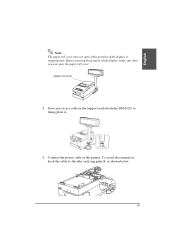
Before securing the position of the display, make sure that you can open if the position of the printer. Connect the power cable of the display is inappropriate. To avoid disconnection, hook the cable to fixing plate A. 9. English Note: The paper roll cover may not open the paper roll cover. paper roll cover 8. Store any excess cable in the support and attach the DM-D210 to the tabs on fixing plate B, as shown below. 19
Before securing the position of the display, make sure that you can open if the position of the printer. Connect the power cable of the display is inappropriate. To avoid disconnection, hook the cable to fixing plate A. 9. English Note: The paper roll cover may not open the paper roll cover. paper roll cover 8. Store any excess cable in the support and attach the DM-D210 to the tabs on fixing plate B, as shown below. 19

Installation Manual
Page 22
... extension) Assembling steps using the "DM-D pole unit for TM printers (Type A)" (DP-502). These items are used when the DM-D210 is used with the "DM-D pole unit for TM printers (Type A)" (DP-502), and Velcro tapes or screws. Attaching to Other TM Printers When using with other TM printers, the DM-D210 can be attached to the bottom...
... extension) Assembling steps using the "DM-D pole unit for TM printers (Type A)" (DP-502). These items are used when the DM-D210 is used with the "DM-D pole unit for TM printers (Type A)" (DP-502), and Velcro tapes or screws. Attaching to Other TM Printers When using with other TM printers, the DM-D210 can be attached to the bottom...

Installation Manual
Page 23
Pass the cable for extension, insert the tab on support B into the hole on support C until you feel it click. Connect the cable for the DM-D210 to the DM-D210. When using support B for the DM-D210 through the hole on the TM printer. 21 When using support B for the DM-D210 through support C, and attach support C to the DC connector on fixing plate A, and fix the cable at the bottom as shown below. 4. English 2. Pass the cable for extension 3.
Pass the cable for extension, insert the tab on support B into the hole on support C until you feel it click. Connect the cable for the DM-D210 to the DM-D210. When using support B for the DM-D210 through the hole on the TM printer. 21 When using support B for the DM-D210 through support C, and attach support C to the DC connector on fixing plate A, and fix the cable at the bottom as shown below. 4. English 2. Pass the cable for extension 3.

Installation Manual
Page 25
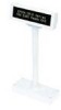
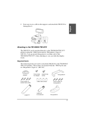
The DM-D210 with the DM-D stand can be used to attach the DM-D210 to the DM-D stand. English Attaching to the DM-D stand The DM-D210 can be connected to a TM printer, or be attached directly to the DM-D stand using the DM-D stand. DM-D stand extension cable for DM Customer Display " (DP-210). Required items The following items are used as a stand alone...
The DM-D210 with the DM-D stand can be used to attach the DM-D210 to the DM-D stand. English Attaching to the DM-D stand The DM-D210 can be connected to a TM printer, or be attached directly to the DM-D stand using the DM-D stand. DM-D stand extension cable for DM Customer Display " (DP-210). Required items The following items are used as a stand alone...

Installation Manual
Page 26
... lines) inch-type millimeter-type RS-232C connector installation screw 24 Connectors for the DM-D stand The connectors for the DM-D stand are as follows: computer connector display connector printer connector power supply unit connector extension cable connector Note: The DM-D stand comes with the included millimeter-type screws using a hex screwdriver (5mm). To distinguish...
... lines) inch-type millimeter-type RS-232C connector installation screw 24 Connectors for the DM-D stand The connectors for the DM-D stand are as follows: computer connector display connector printer connector power supply unit connector extension cable connector Note: The DM-D stand comes with the included millimeter-type screws using a hex screwdriver (5mm). To distinguish...
Installation Manual
Page 27
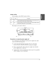
... when connecting both the TM printer and the DM-D stand. (Default setting) Set the jumpers as in the left column when using the power supply unit To avoid damage to the DM-D210 and the power supply unit, make sure to note the following points. ❏ Use the optional Seiko Epson products, PS-170, or... to the power supply unit when the power supply unit is not connected.) The jumpers are located as follows: JP2 JP1 Precautions on using the DM-D stand as stand alone. (TM printer is connected. ❏ Unplug the DC cable by holding the connector part.
... when connecting both the TM printer and the DM-D stand. (Default setting) Set the jumpers as in the left column when using the power supply unit To avoid damage to the DM-D210 and the power supply unit, make sure to note the following points. ❏ Use the optional Seiko Epson products, PS-170, or... to the power supply unit when the power supply unit is not connected.) The jumpers are located as follows: JP2 JP1 Precautions on using the DM-D stand as stand alone. (TM printer is connected. ❏ Unplug the DC cable by holding the connector part.

Installation Manual
Page 30
... the other end to the printer connector on the DM-D stand; When using the extension cable for the printer to the power connector on the printer. When not using the extension cable, connect it (with the arrow mark up) to the extension cable connector indicated with the DM-D stand, go to step ... alone, go to step 6. 5. Tighten the screws on both ends of the printer interface cable for power supply packed with "POWER OUT" on the DM-D stand; then connect the other end to fasten them. 6. When using with the printer, connect one end of the cable to the connector on the...
... the other end to the printer connector on the DM-D stand; When using the extension cable for the printer to the power connector on the printer. When not using the extension cable, connect it (with the arrow mark up) to the extension cable connector indicated with the DM-D stand, go to step ... alone, go to step 6. 5. Tighten the screws on both ends of the printer interface cable for power supply packed with "POWER OUT" on the DM-D stand; then connect the other end to fasten them. 6. When using with the printer, connect one end of the cable to the connector on the...

Installation Manual
Page 35
... further if it stops. English Turning and Tilting the DM-D210 You can be moved easily, so do not move it by force, you desire. With the "DM-D pole unit for IR" (DP-504) and the "DM-D pole unit for TM printers (Type B)" (DP-503), the display area maynot face the direction you may damage it... to the base. 330° 36° The display area has the following range of movement: ❏ Tilt...
... further if it stops. English Turning and Tilting the DM-D210 You can be moved easily, so do not move it by force, you desire. With the "DM-D pole unit for IR" (DP-504) and the "DM-D pole unit for TM printers (Type B)" (DP-503), the display area maynot face the direction you may damage it... to the base. 330° 36° The display area has the following range of movement: ❏ Tilt...
