Epson B134101 - DM D210 - Vacuum Fluorescent Display Character Support and Manuals
Get Help and Manuals for this Epson item
View All Support Options Below
Free Epson B134101 manuals!
Problems with Epson B134101?
Ask a Question
Free Epson B134101 manuals!
Problems with Epson B134101?
Ask a Question
Popular Epson B134101 Manual Pages
Installation Manual - Page 4
... attach plural extension supports. Product may cause equipment damage and fire.
❏ Be sure to turn beyond the limits of the display. Doing so may be damaged or cause injury if it to set this equipment on top of this manual. CAUTION:
❏ Do not plug the cable differently from the instruction in locations...
Installation Manual - Page 6

... TM Printers 20 Attaching to the DM-D stand 23 Part Names and Functions 30 Exterior 30 DIP Switch 31 DIP Switch Functions 31 Turning and Tilting the DM-D210 33 Self Test 34 Check Items of Self test 34 Performing Self test 34 Diagnostics 34 Specification 35 General Specifications 35 Electrical Specifications 38 Environmental Specifications 38 Character Specifications...
Installation Manual - Page 7
... how to the DMD210 are turned off. ❏ Do not drop the DM-D210, because you may damage the built-in the box. installation manual
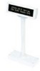
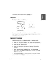
Display (DM-D210)
Make sure that you find anything missing or damaged items, please contact your DM-D210 dealer.
Unpacking
The following points: ❏ Avoid locations that are subject to...
Installation Manual - Page 8
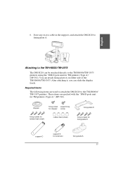
... tapes or screws. (See page 20.) ❏ DM-D stand. You can attach the DM-D210 to extend the length of the DM-D210, an optional extension support is required. You can attach the DM-D210 to
TM-H5000II/TM-J8000 printers using the "DM-D pole unit for DM Customer Display" (DP-110). You can attach...
Installation Manual - Page 10
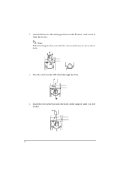
2. Attach the base to the setting position on the support until you feel it with the screws. Insert the tab on the base into the hole on the IR series, and secure it click.
.
8 Pass the cable for the DM-D210 through the base.
4. Note: When attaching the base, note that the corners of the base are set as shown below.
3.
Installation Manual - Page 11
base
support C
fixing screws
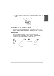
support B (for TM printers (Type B)" (DP-503). Connect the cable for the DM-D210 to the TM-H5000II/TM-J8000 printers using the "DM-D pole unit for TM printers (Type B)" (DP-503). Required items
The following items are packed with the "DM-D pole unit for extension)
9 Attaching to the TM-H5000II/TM-J8000...
Installation Manual - Page 12
When using support B for extension
2.
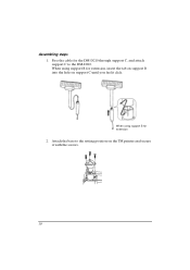
Assembling steps 1. When using support B for the DM-D210 through support C, and attach support C to the setting position on support C until you feel it with the screws.
10 Attach the base to the DM-D210. Pass the cable for extension, insert the tab on support B into the hole on the TM printer and secure it click.
Installation Manual - Page 13
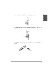
Connect the cable for the DM-D210 through the base.
4. Insert the tab on the base into the hole on the TM printer.
11 English
3. Pass the cable for the DM-D210 to the DM connector on the support until you feel it click.
5.
Installation Manual - Page 14

...
for rubber feet for metallic
(large)
portion
fixing screws for plastic position
support C
support B for TM printers (Type A)" (DP-502). These items are used to attach the DM-D210 to the TM-U375/TM-U950 printers using the "DM-D pole unit for TM printers (Type A)" (DP-502).
Attaching to the TM-U375/TM-U950
The DM...
Installation Manual - Page 15

When using support B for extension
[TM-U375]
[TM-U950]
13 Attach the rubber feet to the DM-D210. Pass the cable for extension, insert the tab on support B into the hole on support C until you feel it click.
2. English
Assembling steps
1. When using support B for the DM-D210 through support C, and attach support C to the printer.
Installation Manual - Page 17
.... English
Attaching to the TM-H6000/TM-U675
The DM-D210 can be attached directly to fixing plate A. 6. Store any excess cable in the support, and attach the DM-D210 to the TM-H6000/TM-U675 printers using the "DM-D pole unit for TM printers (Type A)" (DP-502). You can slide the display freely. Required...
Installation Manual - Page 18

Attach the rubber feet to the printer.
16 When using support B for extension
2. When using support B for extension, insert the tab on support B into the hole on support C until you feel it click. Attach fixing plate B to the printer.
3. Pass the cable for the DM-D210 through support C, and attach support C to the DM-D210. Assembling steps 1.
Installation Manual - Page 21
... cable of the display is inappropriate. Store any excess cable in the support and attach the DM-D210 to the tabs on fixing plate B, as shown below.
19 English
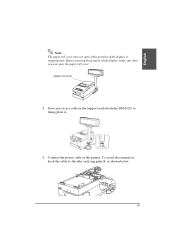
Note...: The paper roll cover may not open the paper roll cover. Before securing the position of the display, make sure that you can open if the position of the printer...
Installation Manual - Page 27
... connected.
❏ Unplug the DC cable by holding the connector part. English
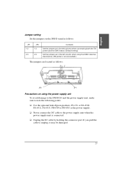
Jumper setting Set the jumpers on the DM-D stand as follows:
JP1 1-2 2-3
JP2 1-2 2-3
Contents
Set the jumpers as in the left columns when connecting both the TM printer and the DM-D stand. (Default setting)
Set the jumpers as in the left column when using the...
Installation Manual - Page 38
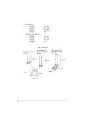
• DM-D210: Height: Width: Depth: Weight:
• DM-D stand (DP-501): Height: Width: Depth: Weight:
91 mm 260 mm 50.5 mm 600 g
53 mm 260 mm 110 mm 385 g
DM-D pole unit for IR (DP-504)
DM-D pole unit for TM printer (Type B) (DP-503)
DM-D pole unit for TM printers (Type A) (DP-502)
129 mm
248 mm
260 mm
50 mm
base 53 mm
78 mm
164 mm
36
Epson B134101 Reviews
We have not received any reviews for Epson yet.