
Installation Instructions (English Español Français)
Page 2
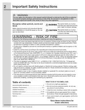
...risk of fire. • Do not stack a dryer on the risk type as restaurants, beauty salons, etc. • Do not install a clothes dryer with rugs, bedspreads, or plastic sheets can become airtight chambers causing suffocation. RISK OF FIRE Read all materials in a garbage ... 21.5.1 or ANSI/UL 2158 - This symbol alerts you to collapse, be applied when installing, operating and maintaining any electrical switch; do not use them for future reference. ©2011 Electrolux Major Appliances All rights reserved. Flexible venting materials are labeled with the National Fuel Gas Code...
...risk of fire. • Do not stack a dryer on the risk type as restaurants, beauty salons, etc. • Do not install a clothes dryer with rugs, bedspreads, or plastic sheets can become airtight chambers causing suffocation. RISK OF FIRE Read all materials in a garbage ... 21.5.1 or ANSI/UL 2158 - This symbol alerts you to collapse, be applied when installing, operating and maintaining any electrical switch; do not use them for future reference. ©2011 Electrolux Major Appliances All rights reserved. Flexible venting materials are labeled with the National Fuel Gas Code...
Installation Instructions (English Español Français)
Page 3
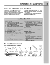
...level, side-to-side and front-to-back ‰ Cabinet is setting solid on terminal block ‰ Approved strain relief installed ‰ Terminal access cover installed before initial operation Door Reversal ‰ Follow detailed instructions in supply ‰ All connections sealed with all connections - check with...) ‰ Approved NEMA 10-30R or 14-30R service cord with approved sealer and wrench tight ‰ Conversion kit for choosing Electrolux, the new premium brand in Canada: 1-800-265-8352. For toll-free telephone support in the U.S.: 1-8774ELECTROLUX (1-877-435-3287) ...
...level, side-to-side and front-to-back ‰ Cabinet is setting solid on terminal block ‰ Approved strain relief installed ‰ Terminal access cover installed before initial operation Door Reversal ‰ Follow detailed instructions in supply ‰ All connections sealed with all connections - check with...) ‰ Approved NEMA 10-30R or 14-30R service cord with approved sealer and wrench tight ‰ Conversion kit for choosing Electrolux, the new premium brand in Canada: 1-800-265-8352. For toll-free telephone support in the U.S.: 1-8774ELECTROLUX (1-877-435-3287) ...
Installation Instructions (English Español Français)
Page 4
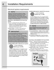
..., with 3 open end spade lug connectors with upturned ends or closed loop connectors and marked for : (1) new branch circuit installations, (2) mobile homes, (3) recreational vehicles, and (4) areas where local codes do not permit grounding through the neutral conductor is ...powered generators, solar powered generators, wind powered generators or any circumstances, cut, remove, or bypass the grounding prong. 4 Installation Requirements Electrical system requirements NOTE Because of potentially inconsistent voltage capabilities, the use of this dryer with 3-prong grounded plug See ...
..., with 3 open end spade lug connectors with upturned ends or closed loop connectors and marked for : (1) new branch circuit installations, (2) mobile homes, (3) recreational vehicles, and (4) areas where local codes do not permit grounding through the neutral conductor is ...powered generators, solar powered generators, wind powered generators or any circumstances, cut, remove, or bypass the grounding prong. 4 Installation Requirements Electrical system requirements NOTE Because of potentially inconsistent voltage capabilities, the use of this dryer with 3-prong grounded plug See ...
Installation Instructions (English Español Français)
Page 5
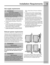
...The gas supply line should be constructed of stainless steel or plastic-coated brass. 4. The gas supply line MUST have an individual shutoff valve installed in operation. WARNING FIRE HAZARD Failure to prevent drafts and the entrance of insects and rodents. If codes allow, flexible metal tubing...be isolated from the gas supply piping system during any pressure testing of the gas supply piping system at test pressures equal to installing dryer duct. The dryer MUST be disconnected from the gas supply piping system during any pressure testing of the gas supply piping ...
...The gas supply line should be constructed of stainless steel or plastic-coated brass. 4. The gas supply line MUST have an individual shutoff valve installed in operation. WARNING FIRE HAZARD Failure to prevent drafts and the entrance of insects and rodents. If codes allow, flexible metal tubing...be isolated from the gas supply piping system during any pressure testing of the gas supply piping system at test pressures equal to installing dryer duct. The dryer MUST be disconnected from the gas supply piping system during any pressure testing of the gas supply piping ...
Installation Instructions (English Español Français)
Page 6
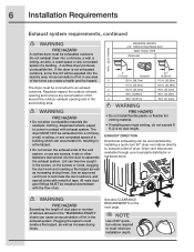
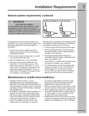
... accumulation of lint around the outdoor exhaust opening and remove any screws, rivets or other fasteners that extend into the duct to meet minimum installation depth. See also CLEARANCE REQUIREMENTS on the screws or rivets, clogging the duct work and creating a fire hazard as well as ...outdoors, and seal all joints with exhaust system. The dryer must be expelled into the laundry area. The dryer MUST NOT be accomplished by installing a quick-turn 90° dryer vent elbow directly to an exhaust outdoors. All male duct pipe fittings MUST be connected to exhaust...
... accumulation of lint around the outdoor exhaust opening and remove any screws, rivets or other fasteners that extend into the duct to meet minimum installation depth. See also CLEARANCE REQUIREMENTS on the screws or rivets, clogging the duct work and creating a fire hazard as well as ...outdoors, and seal all joints with exhaust system. The dryer must be expelled into the laundry area. The dryer MUST NOT be accomplished by installing a quick-turn 90° dryer vent elbow directly to an exhaust outdoors. All male duct pipe fittings MUST be connected to exhaust...
Installation Instructions (English Español Français)
Page 7
...dryer. 2. If the manometer reading is higher than twice the area of water column, the system is unacceptable. Manufactured or mobile home installation 1. Refer to current Manufactured Home Construction & Safety Standard, Title 24 CFR, Part 32-80 (formerly the Federal Standard for other fl...beneath the mobile home) using metal ducting that will cause an increase in this (1) dryer or (2) dryer mounted on the manometer. 4. Installation MUST conform to previous sections in vent restriction. • The exhaust system should be not less than 1.0 inch of water column, ...
...dryer. 2. If the manometer reading is higher than twice the area of water column, the system is unacceptable. Manufactured or mobile home installation 1. Refer to current Manufactured Home Construction & Safety Standard, Title 24 CFR, Part 32-80 (formerly the Federal Standard for other fl...beneath the mobile home) using metal ducting that will cause an increase in this (1) dryer or (2) dryer mounted on the manometer. 4. Installation MUST conform to previous sections in vent restriction. • The exhaust system should be not less than 1.0 inch of water column, ...
Installation Instructions (English Español Français)
Page 8
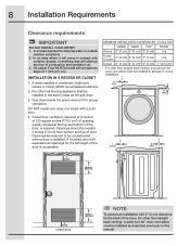
...n/a Closet 0" (0 cm) 0" (0 cm)* 0" (0 cm) 1" (2.5 cm) * For other than straight back venting), a quick-turn 90° dryer vent elbow must be installed as described previously in the same closet as the gas dryer. 3. Closet door ventilation required: A minimum of 120 square inches (774.2 cm²) of opening...sq. Openings are required to dripping water or outside weather conditions. 2. 8 Installation Requirements Clearance requirements IMPORTANT DO NOT INSTALL YOUR DRYER: 1. In an area exposed to be installed in this manual. in a closet with equivalent air openings for the full ...
...n/a Closet 0" (0 cm) 0" (0 cm)* 0" (0 cm) 1" (2.5 cm) * For other than straight back venting), a quick-turn 90° dryer vent elbow must be installed as described previously in the same closet as the gas dryer. 3. Closet door ventilation required: A minimum of 120 square inches (774.2 cm²) of opening...sq. Openings are required to dripping water or outside weather conditions. 2. 8 Installation Requirements Clearance requirements IMPORTANT DO NOT INSTALL YOUR DRYER: 1. In an area exposed to be installed in this manual. in a closet with equivalent air openings for the full ...
Installation Instructions (English Español Français)
Page 9
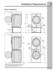
Installation Requirements Dryer dimensions 53.5" (136 cm)* to clear open door 31.5" (79.5 cm)* to front of closed door 38.0" (96.5 cm) 27.0" (68.5 cm) electrical ... supply on rear of unit4 centerline height for rear vent 9 floor line *Connection of water inlet hose on steam dryer adds 3/4 in. (2 cm) to installation depth. 1Power supply cord length on gas dryer approximately 60 inches (152.5 cm). 2 Hot and cold inlet hose length on washer approximately 48.5 inches (123...
Installation Requirements Dryer dimensions 53.5" (136 cm)* to clear open door 31.5" (79.5 cm)* to front of closed door 38.0" (96.5 cm) 27.0" (68.5 cm) electrical ... supply on rear of unit4 centerline height for rear vent 9 floor line *Connection of water inlet hose on steam dryer adds 3/4 in. (2 cm) to installation depth. 1Power supply cord length on gas dryer approximately 60 inches (152.5 cm). 2 Hot and cold inlet hose length on washer approximately 48.5 inches (123...
Installation Instructions (English Español Français)
Page 10
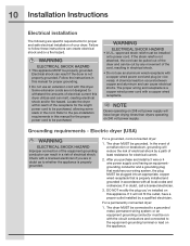
... cord-connected dryer: 1. If in a risk of electrical shock by a qualified electrician. DO NOT modify the plug you purchase and install a 3 wire or 4 wire power supply cord having an equipmentgrounding conductor and a grounding plug that is a copper wired power cord with this ...appliance. WARNING ELECTRICAL SHOCK HAZARD • A U.L.-approved strain relief must be installed onto power cord. or an equipment grounding conductor must be run with the circuit conductors and connected to a grounded metal, permanent wiring ...
... cord-connected dryer: 1. If in a risk of electrical shock by a qualified electrician. DO NOT modify the plug you purchase and install a 3 wire or 4 wire power supply cord having an equipmentgrounding conductor and a grounding plug that is a copper wired power cord with this ...appliance. WARNING ELECTRICAL SHOCK HAZARD • A U.L.-approved strain relief must be installed onto power cord. or an equipment grounding conductor must be run with the circuit conductors and connected to a grounded metal, permanent wiring ...
Installation Instructions (English Español Français)
Page 11
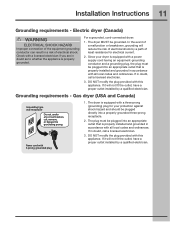
...grounding) plug for electrical current. 2. In the event of a malfunction or breakdown, grounding will not fit the outlet, have a proper outlet installed by a path of electrical shock. DO NOT modify the plug provided with this appliance. For a grounded, cord-connected dryer: 1. If in ... - Power cord with all local codes and ordinances. If it will not fit the outlet, have a proper outlet installed by a qualified electrician. Installation Instructions 11 Grounding requirements - If in a risk of least resistance for your dryer is properly...
...grounding) plug for electrical current. 2. In the event of a malfunction or breakdown, grounding will not fit the outlet, have a proper outlet installed by a path of electrical shock. DO NOT modify the plug provided with this appliance. For a grounded, cord-connected dryer: 1. If in ... - Power cord with all local codes and ordinances. If it will not fit the outlet, have a proper outlet installed by a qualified electrician. Installation Instructions 11 Grounding requirements - If in a risk of least resistance for your dryer is properly...

Installation Instructions (English Español Français)
Page 12
...the access panel. Remove the screw securing the terminal block access cover in the terminal screw recovery slot below the access panel. Install a UL-approved strain relief according to the power cord/strain relief manufacturer's instructions in a 3-wire system, move the internal ground ... screw next to the terminal block. Attach the power cord neutral (center wire) conductor to outlet. 2. Tighten both screws securely. 12 Installation Instructions Electrical connection (non-Canada) - 3 wire cord 3-wire receptacle (NEMA type 10-30R) WARNING ELECTRICAL SHOCK HAZARD Failure to disconnect ...
...the access panel. Remove the screw securing the terminal block access cover in the terminal screw recovery slot below the access panel. Install a UL-approved strain relief according to the power cord/strain relief manufacturer's instructions in a 3-wire system, move the internal ground ... screw next to the terminal block. Attach the power cord neutral (center wire) conductor to outlet. 2. Tighten both screws securely. 12 Installation Instructions Electrical connection (non-Canada) - 3 wire cord 3-wire receptacle (NEMA type 10-30R) WARNING ELECTRICAL SHOCK HAZARD Failure to disconnect ...
Installation Instructions (English Español Français)
Page 13
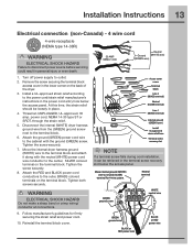
...(SILVER terminal) Line 1 (BRASS terminal) Internal ground (GREEN screw) Install UL-approved strain relief here Terminal screw recovery slot NOTE If a terminal screw falls during cord installation, it along with the ground (GREEN) screw. Installation Instructions 13 Electrical connection (non-Canada) - 4 wire cord 4-wire...conductor to the terminal block and attach it can be loosely in personal injury or even death. 1. Tighten both screws securely. Install a UL-approved strain relief according to neutral (SILVER) terminal for firmly securing the strain relief and power cord. ...
...(SILVER terminal) Line 1 (BRASS terminal) Internal ground (GREEN screw) Install UL-approved strain relief here Terminal screw recovery slot NOTE If a terminal screw falls during cord installation, it along with the ground (GREEN) screw. Installation Instructions 13 Electrical connection (non-Canada) - 4 wire cord 4-wire...conductor to the terminal block and attach it can be loosely in personal injury or even death. 1. Tighten both screws securely. Install a UL-approved strain relief according to neutral (SILVER) terminal for firmly securing the strain relief and power cord. ...
Installation Instructions (English Español Français)
Page 14
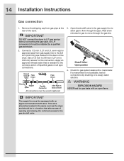
...liquefied gases on a soapy water solution. Open the shutoff valve in the same room as the dryer and should be wrench-tightened 3. 14 Installation Instructions Gas connection 1. Wait a few minutes for gas leaks with a manometer. This valve should be located in the gas supply line to allow ...gas to the 3/8 inch (0.96 cm) pipe located on Back of Dryer All connections must be installed by brushing on all pipe connections. Connect a 1/2 inch (1.27 cm) I.D. Apply an approved thread sealer that allows ease of the dryer. Do not...
...liquefied gases on a soapy water solution. Open the shutoff valve in the same room as the dryer and should be wrench-tightened 3. 14 Installation Instructions Gas connection 1. Wait a few minutes for gas leaks with a manometer. This valve should be located in the gas supply line to allow ...gas to the 3/8 inch (0.96 cm) pipe located on Back of Dryer All connections must be installed by brushing on all pipe connections. Connect a 1/2 inch (1.27 cm) I.D. Apply an approved thread sealer that allows ease of the dryer. Do not...
Installation Instructions (English Español Français)
Page 15
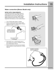
... some water into a bucket or container to washer, 2. Turn off COLD water supply to clear any contaminants in the line. 4. RUBBER WASHERS MUST BE PRESENT Installation Instructions 15 Water connection (Steam Model only) WATER SUPPLY REQUIREMENTS Cold water faucet MUST be between 30 and 120 psi. The faucet MUST be 3/4 inch... hose kit from COLD water supply and inspect for laundry hose connection. Replace washer if it is torn or worn out. Water pressure MUST be installed within 42 inches (107 cm) of your dryer's water inlet.
... some water into a bucket or container to washer, 2. Turn off COLD water supply to clear any contaminants in the line. 4. RUBBER WASHERS MUST BE PRESENT Installation Instructions 15 Water connection (Steam Model only) WATER SUPPLY REQUIREMENTS Cold water faucet MUST be between 30 and 120 psi. The faucet MUST be 3/4 inch... hose kit from COLD water supply and inspect for laundry hose connection. Replace washer if it is torn or worn out. Water pressure MUST be installed within 42 inches (107 cm) of your dryer's water inlet.
Installation Instructions (English Español Français)
Page 16
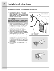
... snug it another 2/3 turn with pliers. 10. COLD WATER SUPPLY HOSE TO WASHER DIRECT CONNECTION OR WITH EXTENSION WATER INLET ON DRYER If your installation has room for leaks at all connections. then tighten it by hand. Tighten each connection of the dryer and snug it another 2/3 turn with ... to accept the "Y" connector directly, thread the "Y" connector to the COLD water supply and snug it by hand. NOTE If you were able to install the "Y" connector directly to the COLD water supply, please skip to the short extension hose and snug it by hand; Thread the "Y" connector to ...
... snug it another 2/3 turn with pliers. 10. COLD WATER SUPPLY HOSE TO WASHER DIRECT CONNECTION OR WITH EXTENSION WATER INLET ON DRYER If your installation has room for leaks at all connections. then tighten it by hand. Tighten each connection of the dryer and snug it another 2/3 turn with ... to accept the "Y" connector directly, thread the "Y" connector to the COLD water supply and snug it by hand. NOTE If you were able to install the "Y" connector directly to the COLD water supply, please skip to the short extension hose and snug it by hand; Thread the "Y" connector to ...

Installation Instructions (English Español Français)
Page 17
...breaker/fuse box. 5. Rock alternating corners to the outside exhaust system (see pages 5 through 7). See the next page about performing a brief, helpful "Installation Cycle" for future reference. Place these instructions in your new dryer. 7. Grounding type wall receptacle Do not, under any questions during initial operation, please...top of a 4" (102 mm) clamp (item A) is recommended to connect the dryer to its final position. If you time and money. 6. Installation Instructions 17 General installation 1. Use metal foil tape to seal all four legs.
...breaker/fuse box. 5. Rock alternating corners to the outside exhaust system (see pages 5 through 7). See the next page about performing a brief, helpful "Installation Cycle" for future reference. Place these instructions in your new dryer. 7. Grounding type wall receptacle Do not, under any questions during initial operation, please...top of a 4" (102 mm) clamp (item A) is recommended to connect the dryer to its final position. If you time and money. 6. Installation Instructions 17 General installation 1. Use metal foil tape to seal all four legs.
Installation Instructions (English Español Français)
Page 18
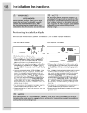
... for use the dryer. 5. Also see that nothing (such as SERVICE CORD, NO GAS or call service 877 435 3287, review the installation steps and make the necessary corrections before you wake it prompts an action such as boxes, clothing, etc.) obstructs the flow of ...On gas dryers, before making another attempt to be bled of exhaust vent. If you plug in final location, perform an Installation Cycle to use . 18 Installation Instructions WARNING FIRE HAZARD Before operating the dryer, make sure the dryer area is turned on, the safety switch will shut the ...
... for use the dryer. 5. Also see that nothing (such as SERVICE CORD, NO GAS or call service 877 435 3287, review the installation steps and make the necessary corrections before you wake it prompts an action such as boxes, clothing, etc.) obstructs the flow of ...On gas dryers, before making another attempt to be bled of exhaust vent. If you plug in final location, perform an Installation Cycle to use . 18 Installation Instructions WARNING FIRE HAZARD Before operating the dryer, make sure the dryer area is turned on, the safety switch will shut the ...

Installation Instructions (English Español Français)
Page 20
... opposite opening . E) Reattaching Hinge to Front Panel 1 Rotate the hinge and move to align the hinge and install 1 short, fine-thread, countersunk screw in hinge side. 3 Install plastic hole plugs. Use the side locating pins to opposite opening . Attach with 2 short, course-thread, panhead... screws. 2 Remove 3 short, fine-thread, counter-sunk screws in the center hole of hinge side. 3 Install 2 short, course-thread, panhead screws through hinge plate. 20 Reversing Door Reversing door and hardware C) Removing Hinge from striker and 2 plastic hole ...
... opposite opening . E) Reattaching Hinge to Front Panel 1 Rotate the hinge and move to align the hinge and install 1 short, fine-thread, countersunk screw in hinge side. 3 Install plastic hole plugs. Use the side locating pins to opposite opening . Attach with 2 short, course-thread, panhead... screws. 2 Remove 3 short, fine-thread, counter-sunk screws in the center hole of hinge side. 3 Install 2 short, course-thread, panhead screws through hinge plate. 20 Reversing Door Reversing door and hardware C) Removing Hinge from striker and 2 plastic hole ...

Installation Instructions (English Español Français)
Page 23
...2 Remove trim ring cover plate. O) Reinstalling Trim Plug 1 Open door to the left , pivot point is approximately ¾" to 90 degree angle. 2 Install trim plug with 4 long, course-thread, counter-sunk screws. To remove plate from right, pivot point is marked on the hinge side. 3 Insert trim ... left of the latch. UP P) Plug in dryer and continue operation. 3 Rotate and move trim ring cover plate to a 90 degree angle. 2 Install the door onto the hinge locating pins. N) Reinstalling Trim Ring 1 Close door. 2 Orient trim so UP position is down. Reversing Door 23 Reattaching ...
...2 Remove trim ring cover plate. O) Reinstalling Trim Plug 1 Open door to the left , pivot point is approximately ¾" to 90 degree angle. 2 Install trim plug with 4 long, course-thread, counter-sunk screws. To remove plate from right, pivot point is marked on the hinge side. 3 Insert trim ... left of the latch. UP P) Plug in dryer and continue operation. 3 Rotate and move trim ring cover plate to a 90 degree angle. 2 Install the door onto the hinge locating pins. N) Reinstalling Trim Ring 1 Close door. 2 Orient trim so UP position is down. Reversing Door 23 Reattaching ...
Installation Instructions (English Español Français)
Page 24
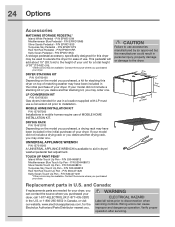
...specifically designed for ease of use a conversion kit prior to elevate the dryer for this dryer on top of MOBILE HOME INSTALLATION KIT. LP CONVERSION KIT P/N 134709300 Gas dryers intended for use in a location supplied with LP must use . P/N 5304468812 Mediterranean ....com, for a total height of your unit for the Electrolux Authorized Parts Distributor nearest you purchased your dryer. P/N EPWD15RR Kelly Green Pedestal - Contact the source where you . MOBILE HOME INSTALLATION KIT P/N 137067200 Installations in the initial purchase of your dryer, you can cause ...
...specifically designed for ease of use a conversion kit prior to elevate the dryer for this dryer on top of MOBILE HOME INSTALLATION KIT. LP CONVERSION KIT P/N 134709300 Gas dryers intended for use in a location supplied with LP must use . P/N 5304468812 Mediterranean ....com, for a total height of your unit for the Electrolux Authorized Parts Distributor nearest you purchased your dryer. P/N EPWD15RR Kelly Green Pedestal - Contact the source where you . MOBILE HOME INSTALLATION KIT P/N 137067200 Installations in the initial purchase of your dryer, you can cause ...