
Use and Care Manual
Page 1
A Use & Care Guide Induction Cooktop Dishwasher 318 200 640 (0604) Rev.
A Use & Care Guide Induction Cooktop Dishwasher 318 200 640 (0604) Rev.
Use and Care Manual
Page 3
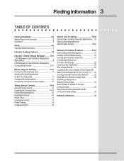
... use 2 Questions 2 Safety 4-6 Important Safety Instructions 4 Induction Cooktop Features 7-8 Induction Cooktop Display Messages .......... 9-10 LED Messages or Light Indicators Displayed by Main Control 9 LED Messages or Light Indicators Displayed by Cooking Zone Controls 9-10 Before Using the Cooktop 11-13 Use the Correct Cookware Type 11 Minimum Pan... Heat Food 21 Cooking Zone Heats Food Too Hot or Not Enough 22 Food Does Not Heat Evenly 22 Poor Cooking Results 22 Cooktop Zone Control Displays E and 2 Digits LED Main Control Displays 00, 03, 04, 05, 06 or 07 ........ 22 Cooking ...
... use 2 Questions 2 Safety 4-6 Important Safety Instructions 4 Induction Cooktop Features 7-8 Induction Cooktop Display Messages .......... 9-10 LED Messages or Light Indicators Displayed by Main Control 9 LED Messages or Light Indicators Displayed by Cooking Zone Controls 9-10 Before Using the Cooktop 11-13 Use the Correct Cookware Type 11 Minimum Pan... Heat Food 21 Cooking Zone Heats Food Too Hot or Not Enough 22 Food Does Not Heat Evenly 22 Poor Cooking Results 22 Cooktop Zone Control Displays E and 2 Digits LED Main Control Displays 00, 03, 04, 05, 06 or 07 ........ 22 Cooking ...

Use and Care Manual
Page 4
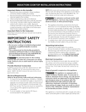
...working of the pacemaker or similar medical device. WARNING To reduce the risk of fire, electrical shock, or injury when using your electric cooktop, follow all tape and packaging wrap before using this unit does cause harmful interference to radio or television reception, which the receiver is...Standard C22.1, Canadian Electrical Never allow children to play with a pacemaker or similar medical device should exercise caution using or standing near an induction unit while it is properly installed and grounded by one or more of the following : This unit has been tested and found to Part...
...working of the pacemaker or similar medical device. WARNING To reduce the risk of fire, electrical shock, or injury when using your electric cooktop, follow all tape and packaging wrap before using this unit does cause harmful interference to radio or television reception, which the receiver is...Standard C22.1, Canadian Electrical Never allow children to play with a pacemaker or similar medical device should exercise caution using or standing near an induction unit while it is properly installed and grounded by one or more of the following : This unit has been tested and found to Part...

Use and Care Manual
Page 7
...7. The coil sensor automatically detects whether the pan is whether turned ON or OFF, the cooktop surface remains cooler than standard ceramic cooktops. Induction cooking heats faster while using less energy. Right Rear Cooking Zone. 4. Left Rear Cooking Zone...been turned OFF. Central Cooking Zone. 6. EFFICIENT - Induction Cooktop Features 7 INDUCTION COOKTOP FEATURES READ THESE INSTRUCTIONS CAREFULLY BEFORE USING THE COOKTOP A COOLER COOKTOP - Central Cooking Zone Control Pads. 9. A unique feature of the Induction Cooktop is magnetic and eliminates accidental "turn-ONs." Left ...
...7. The coil sensor automatically detects whether the pan is whether turned ON or OFF, the cooktop surface remains cooler than standard ceramic cooktops. Induction cooking heats faster while using less energy. Right Rear Cooking Zone. 4. Left Rear Cooking Zone...been turned OFF. Central Cooking Zone. 6. EFFICIENT - Induction Cooktop Features 7 INDUCTION COOKTOP FEATURES READ THESE INSTRUCTIONS CAREFULLY BEFORE USING THE COOKTOP A COOLER COOKTOP - Central Cooking Zone Control Pads. 9. A unique feature of the Induction Cooktop is magnetic and eliminates accidental "turn-ONs." Left ...

Use and Care Manual
Page 8
... up to 99 minutes - (See pages 16 & 17). 19. Left Rear Cooking Zone Control Pads. 8 Central Cooking Zone Control Pads. 9. Cooktop Power Key Pad (See p. 9). 13. 8 Induction Cooktop Features INDUCTION COOKTOP FEATURES (CONT'D) 11 Main Cooktop Controls 16 13 17 POWER 18 15 14 12 Fig 2. 6 7 8 9 10 Cooking Zone Controls (at 5 locations) 20 23 22 21...
... up to 99 minutes - (See pages 16 & 17). 19. Left Rear Cooking Zone Control Pads. 8 Central Cooking Zone Control Pads. 9. Cooktop Power Key Pad (See p. 9). 13. 8 Induction Cooktop Features INDUCTION COOKTOP FEATURES (CONT'D) 11 Main Cooktop Controls 16 13 17 POWER 18 15 14 12 Fig 2. 6 7 8 9 10 Cooking Zone Controls (at 5 locations) 20 23 22 21...

Use and Care Manual
Page 9
Induction Cooktop Display Messages 9 LED MESSAGES OR LIGHT INDICATORS DISPLAYED BY MAIN CONTROL CONTROLS LOCK - To turn OFF (Fig. 10). The cooktop will turn the Controls Lock OFF, touch and hold the POWER key pad for 5 seconds. Each of the five Cooking Zones have separate ON/ ... automatically. A beep will sound and the Power Indicator Light will glow (See Fig. 7). Once the Main Power key pad has been touched to activate the cooktop, touch the corresponding Cooking Zone ON/OFF key pad once to OFF. If the corresponding + (increase) / - (decrease) key pad is switched to active ...
Induction Cooktop Display Messages 9 LED MESSAGES OR LIGHT INDICATORS DISPLAYED BY MAIN CONTROL CONTROLS LOCK - To turn OFF (Fig. 10). The cooktop will turn the Controls Lock OFF, touch and hold the POWER key pad for 5 seconds. Each of the five Cooking Zones have separate ON/ ... automatically. A beep will sound and the Power Indicator Light will glow (See Fig. 7). Once the Main Power key pad has been touched to activate the cooktop, touch the corresponding Cooking Zone ON/OFF key pad once to OFF. If the corresponding + (increase) / - (decrease) key pad is switched to active ...

Use and Care Manual
Page 10
...See pages 14-17 for 10 minutes (See Fig. 13). Once any Cooking Zone has been used for cooking and turned OFF, and if the cooktop surface temperature on any of magnetic material, F (See Fig. 17) will appear in the affected Cooking Zone LED display. L (LOW) should... (or just holding down the Power Level key pad) will provide a Pan Detection message. KEEP WARM - These include 1 2, 3, 4, 5, 6 (fig. 14), 7, 8, 9. 10 Induction Cooktop Display Messages LED MESSAGES OR LIGHT INDICATORS DISPLAYED BY COOKING ZONE CONTROLS (CONT'D) Fig. 14 Fig. 15 Fig. 16 Fig. 17 POWER LEVEL SETTINGS -
...See pages 14-17 for 10 minutes (See Fig. 13). Once any Cooking Zone has been used for cooking and turned OFF, and if the cooktop surface temperature on any of magnetic material, F (See Fig. 17) will appear in the affected Cooking Zone LED display. L (LOW) should... (or just holding down the Power Level key pad) will provide a Pan Detection message. KEEP WARM - These include 1 2, 3, 4, 5, 6 (fig. 14), 7, 8, 9. 10 Induction Cooktop Display Messages LED MESSAGES OR LIGHT INDICATORS DISPLAYED BY COOKING ZONE CONTROLS (CONT'D) Fig. 14 Fig. 15 Fig. 16 Fig. 17 POWER LEVEL SETTINGS -

Use and Care Manual
Page 11
...order to the correct MINIMUM pan size. The 5 Cooking Zones available on the Induction Cooktop require a MINIMUM pan size to always use heavier high quality stainless steel cookware on your Induction Cooktop surface. INFINITE INFINITE NOTE: Pan bottom should not exceed 1/2" (13mm) from ...outer Cooking Zone (Induction) rings INFINITE The thicker outer ring at each Cooking Zone is your not ...
...order to the correct MINIMUM pan size. The 5 Cooking Zones available on the Induction Cooktop require a MINIMUM pan size to always use heavier high quality stainless steel cookware on your Induction Cooktop surface. INFINITE INFINITE NOTE: Pan bottom should not exceed 1/2" (13mm) from ...outer Cooking Zone (Induction) rings INFINITE The thicker outer ring at each Cooking Zone is your not ...

Use and Care Manual
Page 13
... buildup. This will make good contact with the entire surface of the Cooking Zone. Before Using the Cooktop 13 USE QUALITY COOKWARE IN GOOD CONDITION The cookware used with the Induction Cooktop should match the amount of food being prepared. • Do not let pans boil dry. CAUTION ... Prior to : • Use cookware made with the correct material type for Induction Cooking (See Fig. 18). • Use quality cookware with heavier bottoms for better heat distribution allowing for flatness by your cooktop for using cookware as shown in the form of breakage, fusion, or marring that...
... buildup. This will make good contact with the entire surface of the Cooking Zone. Before Using the Cooktop 13 USE QUALITY COOKWARE IN GOOD CONDITION The cookware used with the Induction Cooktop should match the amount of food being prepared. • Do not let pans boil dry. CAUTION ... Prior to : • Use cookware made with the correct material type for Induction Cooking (See Fig. 18). • Use quality cookware with heavier bottoms for better heat distribution allowing for flatness by your cooktop for using cookware as shown in the form of breakage, fusion, or marring that...

Use and Care Manual
Page 14
... Zone by touching either the or key pad. NOTE: If no other key pad is touched within 20 seconds the request to Power ON the cooktop will turn ON. Set the desired power level for 2 seconds (or until a beep sounds). If the key pad is touched the Cooking Zone will start... Surface Controls USING THE TOUCH CONTROL Fig. 22 The recommended way to use the narrow end of your entire fingertip. OPERATING THE COOKING ZONES The Induction cooktop has five Cooking Zones designed for the Cooking Zone (See Fig. 20) are not met the sensors will show 0 indicating no power level for the...
... Zone by touching either the or key pad. NOTE: If no other key pad is touched within 20 seconds the request to Power ON the cooktop will turn ON. Set the desired power level for 2 seconds (or until a beep sounds). If the key pad is touched the Cooking Zone will start... Surface Controls USING THE TOUCH CONTROL Fig. 22 The recommended way to use the narrow end of your entire fingertip. OPERATING THE COOKING ZONES The Induction cooktop has five Cooking Zones designed for the Cooking Zone (See Fig. 20) are not met the sensors will show 0 indicating no power level for the...
Use and Care Manual
Page 16
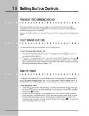
... FEATURE The Warm feature may be useful in the kitchen if a recipe calls for keeping track of time. The Cooking Zone will sound indicating that induction may be used with remaining minutes. To Set the Minute Timer: 1. Once the Timer LED displays the desired amount of the Cooking Zones. Keep in... is up to any of time, release the UP or DOWN Arrow key pads. 16 Setting Surface Controls PREHEAT RECOMMENDATIONS When preheating a pan on the cooktop always watch carefully. Whenever using the cooktop the user should always pay attention to 99 minutes). 2.
... FEATURE The Warm feature may be useful in the kitchen if a recipe calls for keeping track of time. The Cooking Zone will sound indicating that induction may be used with remaining minutes. To Set the Minute Timer: 1. Once the Timer LED displays the desired amount of the Cooking Zones. Keep in... is up to any of time, release the UP or DOWN Arrow key pads. 16 Setting Surface Controls PREHEAT RECOMMENDATIONS When preheating a pan on the cooktop always watch carefully. Whenever using the cooktop the user should always pay attention to 99 minutes). 2.

Use and Care Manual
Page 17
.... The Lock Indicator Light above the key pad will turn ON indicating the cooktop is unlocked. Setting Surface Controls 17 MINUTE TIMER To Cancel the Minute Timer: 1. LOCKING THE CONTROLS The Induction Cooktop may be used (See Fig. 4). 2. The Power Indicator Light located above... the key pad will keep any of the other Cooktop functions may now activate any Cooking Zone or Cooktop functions from accidentally being accidentally turned ON (See...
.... The Lock Indicator Light above the key pad will turn ON indicating the cooktop is unlocked. Setting Surface Controls 17 MINUTE TIMER To Cancel the Minute Timer: 1. LOCKING THE CONTROLS The Induction Cooktop may be used (See Fig. 4). 2. The Power Indicator Light located above... the key pad will keep any of the other Cooktop functions may now activate any Cooking Zone or Cooktop functions from accidentally being accidentally turned ON (See...
Use and Care Manual
Page 18
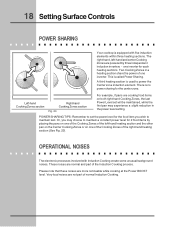
18 Setting Surface Controls POWER SHARING Your cooktop is equipped with Induction Cooking create some unusual background noises. one of the Cooking Zones of the left -hand and center Cooking Zones are more noticeable while cooking at ... For example, if pans are cooking food items on one of the Cooking Zones of one inverter. OPERATIONAL NOISES The electronic processes involved with five induction elements within three heating sections. Two Cooking Zones in the power level setting. There is called Power Sharing. This is no power sharing for 2 food...
18 Setting Surface Controls POWER SHARING Your cooktop is equipped with Induction Cooking create some unusual background noises. one of the Cooking Zones of the left -hand and center Cooking Zones are more noticeable while cooking at ... For example, if pans are cooking food items on one of the Cooking Zones of one inverter. OPERATIONAL NOISES The electronic processes involved with five induction elements within three heating sections. Two Cooking Zones in the power level setting. There is called Power Sharing. This is no power sharing for 2 food...

Use and Care Manual
Page 21
... result of the Cooking Zones and the entire Cooktop OFF after any Cooking Zone has been in your cooktop. COOKING ZONE DOES NOT HEAT FOOD • No cookware was placed on the Cooking Zone or cookware material type incorrect for Induction Cooking (See Figs. 18 & 20). •...; Cookware bottom not large enough for 18 hours. • Cooktop internal heat sensor has detected high temperatures inside the appliance. Check steps under "Entire cooktop does not operate" in poor condition (See Figs...
... result of the Cooking Zones and the entire Cooktop OFF after any Cooking Zone has been in your cooktop. COOKING ZONE DOES NOT HEAT FOOD • No cookware was placed on the Cooking Zone or cookware material type incorrect for Induction Cooking (See Figs. 18 & 20). •...; Cookware bottom not large enough for 18 hours. • Cooktop internal heat sensor has detected high temperatures inside the appliance. Check steps under "Entire cooktop does not operate" in poor condition (See Figs...

Use and Care Manual
Page 22
.... POOR COOKING RESULTS • Many factors affect cooking results. COOKING ZONE LED CONTINUOUSLY FLASHES F • Induction Cooktop pan detection sensors do not see the correct cookware. COOKTOP ZONE CONTROL DISPLAYS E AND 2 DIGITS LED MAIN CONTROL DISPLAYS • Induction Cooktop main control has detected a fault or error condition. If fault recurs, record fault number and turn...
.... POOR COOKING RESULTS • Many factors affect cooking results. COOKING ZONE LED CONTINUOUSLY FLASHES F • Induction Cooktop pan detection sensors do not see the correct cookware. COOKTOP ZONE CONTROL DISPLAYS E AND 2 DIGITS LED MAIN CONTROL DISPLAYS • Induction Cooktop main control has detected a fault or error condition. If fault recurs, record fault number and turn...

Installation Instructions
Page 1
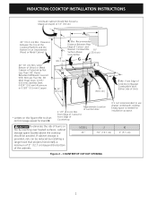
INDUCTION COOKTOP INSTALLATION INSTRUCTIONS INSTALLATION AND SERVICE MUST BE PERFORMED BY A QUALIFIED INSTALLER. LENGTH B. LENGTH C D 36¾ (93.3) 21½ (54.6) 2 (5.1) 2¾ (7) 345/8 (87.9) F. Min. Max. 357/8 (91.1) 36 (91.4) 203/8 (51.8) 20½ (52.1) I C Fresh air intake** H 4" X 8" (10.2 cm x .... B English - IMPORTANT: SAVE FOR LOCAL ELECTRICAL INSPECTOR'S USE. READ AND SAVE THESE INSTRUCTIONS FOR FUTURE REFERENCE. Printed in inches and (cm). WARNING FOR YOUR SAFETY: Do not store or use gasoline or other appliance. WIDTH DEPTH E. WIDTH Min. pages...
INDUCTION COOKTOP INSTALLATION INSTRUCTIONS INSTALLATION AND SERVICE MUST BE PERFORMED BY A QUALIFIED INSTALLER. LENGTH B. LENGTH C D 36¾ (93.3) 21½ (54.6) 2 (5.1) 2¾ (7) 345/8 (87.9) F. Min. Max. 357/8 (91.1) 36 (91.4) 203/8 (51.8) 20½ (52.1) I C Fresh air intake** H 4" X 8" (10.2 cm x .... B English - IMPORTANT: SAVE FOR LOCAL ELECTRICAL INSPECTOR'S USE. READ AND SAVE THESE INSTRUCTIONS FOR FUTURE REFERENCE. Printed in inches and (cm). WARNING FOR YOUR SAFETY: Do not store or use gasoline or other appliance. WIDTH DEPTH E. WIDTH Min. pages...
Installation Instructions
Page 2
INDUCTION COOKTOP INSTALLATION INSTRUCTIONS Overhead Cabinet Should Not Exceed a Maximum Depth of Cutout and Nearest Combustible 10" Surface Above ( 25.4 cm) Countertop 18" G (45.7 cm) I H 24" (61 cm) 12" (30.5 cm) J Min. K Min. Recommended Distance Between Rear Edge of 13" (33 cm) 30" (76.2 cm) Min. From Edge of Cooktop... Box 2 1/2" (6.4 cm) Min. MODEL 36" J 7½" (19.1 cm) K 2" (5.1 cm) Figure 2 - From Edge of Cutout to Front Edge of Unit). * Letters on this figure refer to use drawer underneath cooktop. Approximate Location of the cabinets. If cabinet ...
INDUCTION COOKTOP INSTALLATION INSTRUCTIONS Overhead Cabinet Should Not Exceed a Maximum Depth of Cutout and Nearest Combustible 10" Surface Above ( 25.4 cm) Countertop 18" G (45.7 cm) I H 24" (61 cm) 12" (30.5 cm) J Min. K Min. Recommended Distance Between Rear Edge of 13" (33 cm) 30" (76.2 cm) Min. From Edge of Cooktop... Box 2 1/2" (6.4 cm) Min. MODEL 36" J 7½" (19.1 cm) K 2" (5.1 cm) Figure 2 - From Edge of Cutout to Front Edge of Unit). * Letters on this figure refer to use drawer underneath cooktop. Approximate Location of the cabinets. If cabinet ...
Installation Instructions
Page 3
...No. 70- Unpack and visually inspect the cooktop. 2. Unpacking Instructions 1. Remove all instructions contained in the Use and Care Guide. NOTE: Wire sizes and connections must be located as follows. INDUCTION COOKTOP INSTALLATION INSTRUCTIONS Important Notes to the fused disconnect... (or circuit breaker) box through flexible armored or nonmetallic sheathed cable. It is made . Approved cooktops and built-in accordance with the National ...
...No. 70- Unpack and visually inspect the cooktop. 2. Unpacking Instructions 1. Remove all instructions contained in the Use and Care Guide. NOTE: Wire sizes and connections must be located as follows. INDUCTION COOKTOP INSTALLATION INSTRUCTIONS Important Notes to the fused disconnect... (or circuit breaker) box through flexible armored or nonmetallic sheathed cable. It is made . Approved cooktops and built-in accordance with the National ...

Installation Instructions
Page 4
...the wire gauge alone. 4 The current carrying capacity of the 4-wire electrical system. Failure to heed this warning may not ground the cooktop through the neutral (white) wire if cooktop is used in figure 4. Green Wire (Ground) U.L.-Listed Conduit Connector Cable from Power Supply White Wire (Neutral) Red Wires Black ...shown in a new branch circuit installation (1996 NEC), mobile home, recreational vehicle, or where local codes DO NOT permit grounding to a gas supply pipe. INDUCTION COOKTOP INSTALLATION INSTRUCTIONS DO NOT ground to the neutral (white) wire (see figure 3): 1.
...the wire gauge alone. 4 The current carrying capacity of the 4-wire electrical system. Failure to heed this warning may not ground the cooktop through the neutral (white) wire if cooktop is used in figure 4. Green Wire (Ground) U.L.-Listed Conduit Connector Cable from Power Supply White Wire (Neutral) Red Wires Black ...shown in a new branch circuit installation (1996 NEC), mobile home, recreational vehicle, or where local codes DO NOT permit grounding to a gas supply pipe. INDUCTION COOKTOP INSTALLATION INSTRUCTIONS DO NOT ground to the neutral (white) wire (see figure 3): 1.

Installation Instructions
Page 5
...use caulking compound; Install the retainer brackets. Model and Serial Number Location The serial plate is located under the cooktop. Visually inspect the cooktop for or making inquires about your Use and Care Guide. See Figure 6. Before You Call for Service Read ...hot enough to meet local codes or, in heat damage or fire (see Figure 6). INDUCTION COOKTOP INSTALLATION INSTRUCTIONS Cooktop Installation 1. cooktop should be installed, to burn you time and expense. Cooktop Countertop Nylon spacer Retainer bracket Figure 6 Nylon spacer (6) Position brackets on the edges of...
...use caulking compound; Install the retainer brackets. Model and Serial Number Location The serial plate is located under the cooktop. Visually inspect the cooktop for or making inquires about your Use and Care Guide. See Figure 6. Before You Call for Service Read ...hot enough to meet local codes or, in heat damage or fire (see Figure 6). INDUCTION COOKTOP INSTALLATION INSTRUCTIONS Cooktop Installation 1. cooktop should be installed, to burn you time and expense. Cooktop Countertop Nylon spacer Retainer bracket Figure 6 Nylon spacer (6) Position brackets on the edges of...


