User Guide
Page 3
... NOT in the Kit 7 EVGA P55 SLI Motherboard 8 Motherboard Specifications 8 Hardware Installation 10 Safety Instructions 10 Preparing the Motherboard 11 Installing the CPU 11 Installing the CPU Fan 12 Installing System Memory (DIMMs 13 Installing the Motherboard 13 Installing the I/O Shield 14 Securing the Motherboard into a System Case 15 Connecting Cables 15 24-pin ATX Power (PW1 16 8-pin...
... NOT in the Kit 7 EVGA P55 SLI Motherboard 8 Motherboard Specifications 8 Hardware Installation 10 Safety Instructions 10 Preparing the Motherboard 11 Installing the CPU 11 Installing the CPU Fan 12 Installing System Memory (DIMMs 13 Installing the Motherboard 13 Installing the I/O Shield 14 Securing the Motherboard into a System Case 15 Connecting Cables 15 24-pin ATX Power (PW1 16 8-pin...
User Guide
Page 5
Assertion Width 38 Restore on AC Power Loss 38 Hardware Health Configure 38 H/W Health Function 38 CPU Fan Mode Setting 39 Frequency/Voltage Control Menu 39 Memory Configure 39 CPU Configuration 40 Installing Drivers and Software 41 Windows XP/Vista/7 Driver Installation 41 Appendix A. POST Codes for the EVGA P55 SLI Motherboard 42 EVGA P55 SLI Motherboard Palette Snooping 35 PCI IDE BusMaster 35 OffBoard PCI/ISA IDE Card 35 Boot Configuration Features 36 Boot Device Priority 36 Hard Disk Drives 36 Power Management Features 37 ACPI Configuration 37 SLP_S4# Min.
Assertion Width 38 Restore on AC Power Loss 38 Hardware Health Configure 38 H/W Health Function 38 CPU Fan Mode Setting 39 Frequency/Voltage Control Menu 39 Memory Configure 39 CPU Configuration 40 Installing Drivers and Software 41 Windows XP/Vista/7 Driver Installation 41 Appendix A. POST Codes for the EVGA P55 SLI Motherboard 42 EVGA P55 SLI Motherboard Palette Snooping 35 PCI IDE BusMaster 35 OffBoard PCI/ISA IDE Card 35 Boot Configuration Features 36 Boot Device Priority 36 Hard Disk Drives 36 Power Management Features 37 ACPI Configuration 37 SLP_S4# Min.
User Guide
Page 7
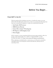
... it does not contain the following items that must be purchased separately to make the motherboard functional. Intel Socket 1156 Processor DDR3 System Memory Socket 1156 or Socket 775 Cooling fan PCI Express or PCI ...EVGA assumes you will need to allow for proper system functionality. For a full list of supported CPU's on this motherboard, please visit http://www.evga.com/support/motherboard/. Parts NOT in a system case, you have purchased all the hardware necessary to install and connect your new EVGA P55 SLI Motherboard. EVGA P55 SLI Motherboard...
... it does not contain the following items that must be purchased separately to make the motherboard functional. Intel Socket 1156 Processor DDR3 System Memory Socket 1156 or Socket 775 Cooling fan PCI Express or PCI ...EVGA assumes you will need to allow for proper system functionality. For a full list of supported CPU's on this motherboard, please visit http://www.evga.com/support/motherboard/. Parts NOT in a system case, you have purchased all the hardware necessary to install and connect your new EVGA P55 SLI Motherboard. EVGA P55 SLI Motherboard...
User Guide
Page 8
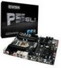
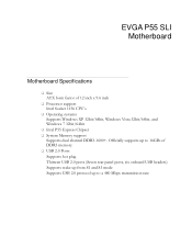
Officially supports up to a 480 Mbps transmission rate EVGA P55 SLI Motherboard Motherboard Specifications Size ATX form factor of DDR3 memory. USB 2.0 Ports Supports hot plug Thirteen USB 2.0 ports (Seven rear panel ports, six onboard USB headers) Supports wake-up from S1 and S3 mode ... Processor support Intel Socket 1156 CPU's Operating systems: Supports Windows XP 32bit/64bit, Windows Vista 32bit/64bit, and Windows 7 32bit/64bit Intel P55 Express Chipset System Memory support Supports dual channel DDR3-1600+.
Officially supports up to a 480 Mbps transmission rate EVGA P55 SLI Motherboard Motherboard Specifications Size ATX form factor of DDR3 memory. USB 2.0 Ports Supports hot plug Thirteen USB 2.0 ports (Seven rear panel ports, six onboard USB headers) Supports wake-up from S1 and S3 mode ... Processor support Intel Socket 1156 CPU's Operating systems: Supports Windows XP 32bit/64bit, Windows Vista 32bit/64bit, and Windows 7 32bit/64bit Intel P55 Express Chipset System Memory support Supports dual channel DDR3-1600+.
User Guide
Page 10
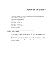
Remember to remove power off your computer by disconnecting the AC main source before removing or installing any equipment from/to the computer chassis. Hardware Installation This section will guide you through the installation of fire, electric shocks, and injury, always follow basic safety precautions. The topics covered in this section are: Preparing the motherboard Installing the CPU Installing the CPU fan Installing the memory Installing the motherboard Connecting cables Safety Instructions To reduce the risk of the motherboard.
Remember to remove power off your computer by disconnecting the AC main source before removing or installing any equipment from/to the computer chassis. Hardware Installation This section will guide you through the installation of fire, electric shocks, and injury, always follow basic safety precautions. The topics covered in this section are: Preparing the motherboard Installing the CPU Installing the CPU fan Installing the memory Installing the motherboard Connecting cables Safety Instructions To reduce the risk of the motherboard.
User Guide
Page 13
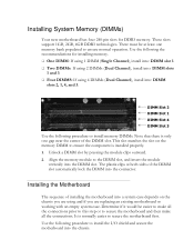
...DIMM slot. Unlock a DIMM slot by pressing the module clips outward. 2. Use the following the recommendations for DDR3 memory. Installing System Memory (DIMMs) Your new motherboard has four 240-pin slots for installing memory. One DIMM: If using 1 DIMM (Single Channel), install into: DIMM slot 1. Two... at both sides of the DIMM slot automatically lock the DIMM into the connector. Installing the Motherboard The sequence of the DIMM slot. It is only one memory bank populated to ensure the component is installed properly. 1. The plastic clips at least one...
...DIMM slot. Unlock a DIMM slot by pressing the module clips outward. 2. Use the following the recommendations for DDR3 memory. Installing System Memory (DIMMs) Your new motherboard has four 240-pin slots for installing memory. One DIMM: If using 1 DIMM (Single Channel), install into: DIMM slot 1. Two... at both sides of the DIMM slot automatically lock the DIMM into the connector. Installing the Motherboard The sequence of the DIMM slot. It is only one memory bank populated to ensure the component is installed properly. 1. The plastic clips at least one...
User Guide
Page 24
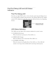
... may be failing to boot. This Debug LED will remain on . Debug LED with CPU Temperature Monitor LED Status Indicators The LEDs near the 24pin ATX connector indicate the system's status. POWER LED (Green): When the System is powered on: This LED is on. DIMM LED (Orange): When the... Memory slot is functional: This LED is on. STANDBY LED (Blue): When the System is in Standby Mode: This LED is on as long as ...
... may be failing to boot. This Debug LED will remain on . Debug LED with CPU Temperature Monitor LED Status Indicators The LEDs near the 24pin ATX connector indicate the system's status. POWER LED (Green): When the System is powered on: This LED is on. DIMM LED (Orange): When the... Memory slot is functional: This LED is on. STANDBY LED (Blue): When the System is in Standby Mode: This LED is on as long as ...
User Guide
Page 27
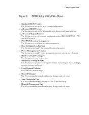
...; Hardware Health Configure Use this menu to view system vitals. Frequency/Voltage Control Use this menu to optimize system performance and configure clocks, voltages, memory timings, and more. Load Optimal Defaults Load default system settings. Discard Changes Use this command to abandon all setting changes and exit setup...
...; Hardware Health Configure Use this menu to view system vitals. Frequency/Voltage Control Use this menu to optimize system performance and configure clocks, voltages, memory timings, and more. Load Optimal Defaults Load default system settings. Discard Changes Use this command to abandon all setting changes and exit setup...

User Guide
Page 28
...(TM) CPU Speed :2666MHz Count :1 750 @ 2.67GHz Help Item Use [ENTER] , [TAB] Or [SHIFT-TAB] to position the selector in the option you choose. System Memory Size :4088MB System Time System Date [13:37:00] [Fri 07/16/2010] Move Enter:Select +/-/:Value F10:Save ESC:Exit F1:General Help F5...
...(TM) CPU Speed :2666MHz Count :1 750 @ 2.67GHz Help Item Use [ENTER] , [TAB] Or [SHIFT-TAB] to position the selector in the option you choose. System Memory Size :4088MB System Time System Date [13:37:00] [Fri 07/16/2010] Move Enter:Select +/-/:Value F10:Save ESC:Exit F1:General Help F5...

User Guide
Page 35
A setting of [Auto] works for legacy ISA devices. Reserved Memory Size This option allows you to specify the size of PCI/ISA external cards. DMA Channel The various DMA settings allow you to reserve IRQ's ...if necessary, it is installed. OffBoard PCI/ISA IDE Card This function allows manual override of the memory block to reserve for most devices. PCI IDE BusMaster This function allows the BIOS to use PCI BusMastering for reading or writing to leave this...
A setting of [Auto] works for legacy ISA devices. Reserved Memory Size This option allows you to specify the size of PCI/ISA external cards. DMA Channel The various DMA settings allow you to reserve IRQ's ...if necessary, it is installed. OffBoard PCI/ISA IDE Card This function allows manual override of the memory block to reserve for most devices. PCI IDE BusMaster This function allows the BIOS to use PCI BusMastering for reading or writing to leave this...

User Guide
Page 38
... System Temperature Sensor :34C/93F :48C/118F :34C/93F CPU Fan Speed Power Fan Speed Chassis Fan Speed :3264 RPM :1337 RPM :3864 RPM VCore Memory CPU VTT PCH +5V :1.337 V :1.481 V :1.021 V :1.031 V :4.961 V Help Item Enables Hardware Health Monitoring Device. Hardware Health Configure H/W Health Function This will enable or...
... System Temperature Sensor :34C/93F :48C/118F :34C/93F CPU Fan Speed Power Fan Speed Chassis Fan Speed :3264 RPM :1337 RPM :3864 RPM VCore Memory CPU VTT PCH +5V :1.337 V :1.481 V :1.021 V :1.031 V :4.961 V Help Item Enables Hardware Health Monitoring Device. Hardware Health Configure H/W Health Function This will enable or...
User Guide
Page 39
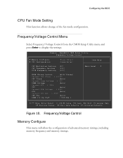
... the BIOS CPU Fan Mode Setting This function allows change of advanced memory timings, including memory frequency and memory timings. AwardBIOS CMOS Setup Utility Frequency/Voltage Control Memory Configure CPU Configuration [Press Enter] [Press Enter] CPU ...Multiplier Setting CPU Frequency Setting PCIE Frequency Setting [20] [133] [100] EVGA VDroop Control [With VDroop] Current CPU VCore : 1.33700V CPU VCore [...
... the BIOS CPU Fan Mode Setting This function allows change of advanced memory timings, including memory frequency and memory timings. AwardBIOS CMOS Setup Utility Frequency/Voltage Control Memory Configure CPU Configuration [Press Enter] [Press Enter] CPU ...Multiplier Setting CPU Frequency Setting PCIE Frequency Setting [20] [133] [100] EVGA VDroop Control [With VDroop] Current CPU VCore : 1.33700V CPU VCore [...

User Guide
Page 43
... System Management interrupt vector Uncompress and initialize BIOS module Initialize devices primary Initialize devices secondary Initialize output devices Allocate memory for ADM module Initialize silent boot module Display sign-on message Initialize USB controller Initialize DMAC-1 & DMAC-2 Initialize real... time clock Test system memory Initialization of chipset registers Detect coprocessor Update CMOS memory size Initialize NUM-LOCK Initialize Int-13 Initialize IPL devices Generate and write contents of ESCD Log...
... System Management interrupt vector Uncompress and initialize BIOS module Initialize devices primary Initialize devices secondary Initialize output devices Allocate memory for ADM module Initialize silent boot module Display sign-on message Initialize USB controller Initialize DMAC-1 & DMAC-2 Initialize real... time clock Test system memory Initialization of chipset registers Detect coprocessor Update CMOS memory size Initialize NUM-LOCK Initialize Int-13 Initialize IPL devices Generate and write contents of ESCD Log...

User Guide
Page 44
... 19 boot End of POST initialization Save system context for ACPI Pass control to OS Show CPU Temp (if enabled) EVGA Glossary of Terms ACPI - Basic Input Output System CD-ROM - Complementary Metal-Oxide Semiconductor CPU - Double Data Rate 2 DDR3 - Dynamic... Data Rate 3 DIMM - Digital Video Interface FDC - Gigahertz GPU - Digital Versatile Disc DVI - Floppy Disk Controller FSB - GHz - Dual In-line Memory Module DRAM - Dry Ice Cooling DDR2 - Front Side Bus FTW - Graphics Processing Unit Central Processing Unit D-ICE - For The Win! Advanced Configuration and ...
... 19 boot End of POST initialization Save system context for ACPI Pass control to OS Show CPU Temp (if enabled) EVGA Glossary of Terms ACPI - Basic Input Output System CD-ROM - Complementary Metal-Oxide Semiconductor CPU - Double Data Rate 2 DDR3 - Dynamic... Data Rate 3 DIMM - Digital Video Interface FDC - Gigahertz GPU - Digital Versatile Disc DVI - Floppy Disk Controller FSB - GHz - Dual In-line Memory Module DRAM - Dry Ice Cooling DDR2 - Front Side Bus FTW - Graphics Processing Unit Central Processing Unit D-ICE - For The Win! Advanced Configuration and ...