
Visual Guide
Page 2
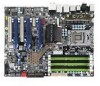
...Close the load plate and with the POST screen on your monitor. It is in to begin powering up the load plate. After removing the EVGA X58 SLITM from its original position. 3 a. Plug in power connectors to a nonconductive surface. Power connector types will now be greeted with light ... Connector to assist you should now be lit on the hard disk drive connection type. Press the onboard Clear CMOS button b. Install one of the SATA Connectors or to the IDE Connector depending on the motherboard. IDE Connection c. Unhook the socket lever and lift up the system...
...Close the load plate and with the POST screen on your monitor. It is in to begin powering up the load plate. After removing the EVGA X58 SLITM from its original position. 3 a. Plug in power connectors to a nonconductive surface. Power connector types will now be greeted with light ... Connector to assist you should now be lit on the hard disk drive connection type. Press the onboard Clear CMOS button b. Install one of the SATA Connectors or to the IDE Connector depending on the motherboard. IDE Connection c. Unhook the socket lever and lift up the system...

User Guide
Page 4
Connecting IDE Hard Disk Drives 24 Connecting Serial ATA Cables 25 Connecting Internal Headers 26 Front Panel Header 26 IEEE1394a (Firewire 27 USB Headers 28 Audio ...29 Fan Connections 30 ...
Connecting IDE Hard Disk Drives 24 Connecting Serial ATA Cables 25 Connecting Internal Headers 26 Front Panel Header 26 IEEE1394a (Firewire 27 USB Headers 28 Audio ...29 Fan Connections 30 ...

User Guide
Page 8
... Intentions of the Kit This kit provides you have an operating system. When replacing a motherboard in a system case, you will not need to reinstall an operating system even though the current Hard Disk Drive may already have purchased all the hardware necessary to allow for the Microprocessor Graphics Card Power... many of the cables provided in the Kit This kit contains all the necessary parts needed to install and connect your new EVGA X58 SLI Motherboard. If you are replacing a motherboard, you will use most of the cables. Before You Begin... Parts NOT in the kit.
... Intentions of the Kit This kit provides you have an operating system. When replacing a motherboard in a system case, you will not need to reinstall an operating system even though the current Hard Disk Drive may already have purchased all the hardware necessary to allow for the Microprocessor Graphics Card Power... many of the cables provided in the Kit This kit contains all the necessary parts needed to install and connect your new EVGA X58 SLI Motherboard. If you are replacing a motherboard, you will use most of the cables. Before You Begin... Parts NOT in the kit.

User Guide
Page 13
...EVGA X58 SLI Motherboard 3 - 2-Port SATA Power Cables Allows a Molex power connector to adapt to either the front or back panels of the chassis. 1 - 4-Port USB 2.0 Bracket Provides four additional USB ports to a SATA power connector. 1 - IEEE1394a (Firewire) Bracket Provides one connects a single drive to setup the motherboard.... Installation CD Contains drivers and software needed to the motherboard. 1 - SATA Data Cables Used to support the Serial ATA protocol and ...
...EVGA X58 SLI Motherboard 3 - 2-Port SATA Power Cables Allows a Molex power connector to adapt to either the front or back panels of the chassis. 1 - 4-Port USB 2.0 Bracket Provides four additional USB ports to a SATA power connector. 1 - IEEE1394a (Firewire) Bracket Provides one connects a single drive to setup the motherboard.... Installation CD Contains drivers and software needed to the motherboard. 1 - SATA Data Cables Used to support the Serial ATA protocol and ...
User Guide
Page 24
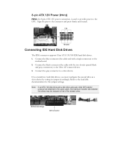
...grey connector to that of the slowest drive. Note: If an ATA-100 disk drive and a disk drive using any other IDE transfer protocol are attached to the same cable, the maximum transfer rate between the drives may be reduced to a slave device. Motherboard Edge IDE Connector Refer to the connector ...and press firmly until seated. 12V Ground Connecting IDE Hard Disk Drives The IDE connector supports Ultra ATA 133/100 IDE hard ...
...grey connector to that of the slowest drive. Note: If an ATA-100 disk drive and a disk drive using any other IDE transfer protocol are attached to the same cable, the maximum transfer rate between the drives may be reduced to a slave device. Motherboard Edge IDE Connector Refer to the connector ...and press firmly until seated. 12V Ground Connecting IDE Hard Disk Drives The IDE connector supports Ultra ATA 133/100 IDE hard ...

User Guide
Page 26
... Ground 7 RST BTN 6 PWR BTN 8 Ground 9 +5V 10 Empty When the system is turn off status, the LED is on. HD_LED Attach the hard disk drive indicator LED cable to these two pins of the hard disks. The system restarts when the RESET switch is in S1, S1, S3, S4 status..., the LED will blink. When the system is pressed. Connecting Internal Headers Front Panel Header The front panel header on this motherboard is one connector used to connect the following four cables. (see Table 2 for pin definitions): PWRLED Attach the front panel power LED cable to these...
... Ground 7 RST BTN 6 PWR BTN 8 Ground 9 +5V 10 Empty When the system is turn off status, the LED is on. HD_LED Attach the hard disk drive indicator LED cable to these two pins of the hard disks. The system restarts when the RESET switch is in S1, S1, S3, S4 status..., the LED will blink. When the system is pressed. Connecting Internal Headers Front Panel Header The front panel header on this motherboard is one connector used to connect the following four cables. (see Table 2 for pin definitions): PWRLED Attach the front panel power LED cable to these...

User Guide
Page 33
...store all the set parameters. These buttons allow you to easily reset the system, turn on /off the system. Clear CMOS Button The motherboard uses the CMOS RAM to easily turn on /off the system, or clear the CMOS. RESET POWER Clear CMOS Button Button Button External Clear... CMOS Button RESET and POWER Button These onboard buttons allow for easy debugging and testing of the hard disk drives and will flicker accordingly. The POWER button with an integrated LED indicates the activity status of the system during troubleshooting situations. When ...
...store all the set parameters. These buttons allow you to easily reset the system, turn on /off the system. Clear CMOS Button The motherboard uses the CMOS RAM to easily turn on /off the system, or clear the CMOS. RESET POWER Clear CMOS Button Button Button External Clear... CMOS Button RESET and POWER Button These onboard buttons allow for easy debugging and testing of the hard disk drives and will flicker accordingly. The POWER button with an integrated LED indicates the activity status of the system during troubleshooting situations. When ...

User Guide
Page 40
...] Press ENTER to the date you enter. This field changes to correspond to display SATA Channel sub-menu IDE Auto-Detect [Press Enter] Extended IDE Drive Access Mode [None} Auto Capacity 0 MB Cylinder 0 Head 0 Precomp 0 Landing Zone 0 Sector 0 Use the Page Up and Page Down keys to scroll through Sat) cannot...
...] Press ENTER to the date you enter. This field changes to correspond to display SATA Channel sub-menu IDE Auto-Detect [Press Enter] Extended IDE Drive Access Mode [None} Auto Capacity 0 MB Cylinder 0 Head 0 Precomp 0 Landing Zone 0 Sector 0 Use the Page Up and Page Down keys to scroll through Sat) cannot...

User Guide
Page 70
...port ACPI sub-system initializing Initialize cache controller Enter setup check and autoconfiguration check up Initialize floppy disk drive Install FDD and setup BIOS data area parameters Initialize hard drive controller IDE device detection Initialize serial ports. Award POST Codes Code Name 5B Awdflash Load 5C Reserved ...6A Reserved 6B Setup 6C Reserved 6D Initialize Floppy 6E Reserved 6F FDD install 70 Reserved 71 Reserved 72 Reserved 73 Initialize Hard Drive 74 Reserved 75 Detect HDD 76 Reserved 77 Detect serial Description If required, will auto load Awdflash.exe in POST Init Initializing...
...port ACPI sub-system initializing Initialize cache controller Enter setup check and autoconfiguration check up Initialize floppy disk drive Install FDD and setup BIOS data area parameters Initialize hard drive controller IDE device detection Initialize serial ports. Award POST Codes Code Name 5B Awdflash Load 5C Reserved ...6A Reserved 6B Setup 6C Reserved 6D Initialize Floppy 6E Reserved 6F FDD install 70 Reserved 71 Reserved 72 Reserved 73 Initialize Hard Drive 74 Reserved 75 Detect HDD 76 Reserved 77 Detect serial Description If required, will auto load Awdflash.exe in POST Init Initializing...

User Guide
Page 73
... Semiconductor CPU - Digital Versatile Disc DVI - For The Win! GHz - High-Definition Multimedia Interface HDR - High Precision Event Timer HT - EVGA Glossary of Electrical and Electronics Engineers Configuring the BIOS Digital Video Interface FDC - Institute of Terms ACPI - Basic Input Output System CD-ROM ... random access memory DVD - Hyper-Threading HSF - Floppy Disk Controller FSB - High Dynamic Range Lighting HPET - Input/Output IDE - Integrated Drive Electronics IEEE - Alternate Frame Rendering APIC - Gigahertz GPU - Double Data Rate 3 DIMM - Hard Disk...
... Semiconductor CPU - Digital Versatile Disc DVI - For The Win! GHz - High-Definition Multimedia Interface HDR - High Precision Event Timer HT - EVGA Glossary of Electrical and Electronics Engineers Configuring the BIOS Digital Video Interface FDC - Institute of Terms ACPI - Basic Input Output System CD-ROM ... random access memory DVD - Hyper-Threading HSF - Floppy Disk Controller FSB - High Dynamic Range Lighting HPET - Input/Output IDE - Integrated Drive Electronics IEEE - Alternate Frame Rendering APIC - Gigahertz GPU - Double Data Rate 3 DIMM - Hard Disk...