
Visual Guide
Page 2
...with light pressure, lower the socket lever back in power connectors to the ON position. d. Color info : CMYK Please match colors to the motherboard. 8 a. 1 a. b. c. b. IDE Connection c. a. Press the onboard Clear CMOS button once then press the green Power Button to either...anti-static mat when handling computer components. It is in one stick of slot depends on your motherboard before installing it on to a nonconductive surface. d. After removing the EVGA X58 SLITM from its original position. 3 a. b. Apply a small, pea-sized drop of thermal...
...with light pressure, lower the socket lever back in power connectors to the ON position. d. Color info : CMYK Please match colors to the motherboard. 8 a. 1 a. b. c. b. IDE Connection c. a. Press the onboard Clear CMOS button once then press the green Power Button to either...anti-static mat when handling computer components. It is in one stick of slot depends on your motherboard before installing it on to a nonconductive surface. d. After removing the EVGA X58 SLITM from its original position. 3 a. b. Apply a small, pea-sized drop of thermal...
User Guide
Page 1
User's Guide EVGA X58 SLI Motherboard
User's Guide EVGA X58 SLI Motherboard

User Guide
Page 3
EVGA X58 SLI Motherboard Table of Contents User's Guide...1 EVGA X58 SLI Motherboard 1 Before You Begin...8 Parts NOT in the Kit 8 Intentions of the Kit 8 EVGA X58 SLI Motherboard 10 Motherboard Specifications 10 Unpacking and Parts Descriptions 12 Unpacking ...12 Equipment ...12 EVGA X58 SLI Motherboard 14 Hardware Installation 17 Safety Instructions 17 Preparing the Motherboard 18 Installing the CPU 18 Installing the CPU Fan 19 Installing System Memory...
EVGA X58 SLI Motherboard Table of Contents User's Guide...1 EVGA X58 SLI Motherboard 1 Before You Begin...8 Parts NOT in the Kit 8 Intentions of the Kit 8 EVGA X58 SLI Motherboard 10 Motherboard Specifications 10 Unpacking and Parts Descriptions 12 Unpacking ...12 Equipment ...12 EVGA X58 SLI Motherboard 14 Hardware Installation 17 Safety Instructions 17 Preparing the Motherboard 18 Installing the CPU 18 Installing the CPU Fan 19 Installing System Memory...

User Guide
Page 5
EVGA X58 SLI Motherboard Hard Disk Boot Priority 44 CD-ROM Device Priority 44 First/Second/Third Boot Device 44 Boot Other Device 45 Boot Up NumLock Status 45 ...
EVGA X58 SLI Motherboard Hard Disk Boot Priority 44 CD-ROM Device Priority 44 First/Second/Third Boot Device 44 Boot Other Device 45 Boot Up NumLock Status 45 ...

User Guide
Page 6
POST Codes for the EVGA X58 SLI Motherboard 66 EVGA Glossary of Terms 74 INT Pin 1/2/3/4/5/6/7/8 Assignment 55 Maximum Payload Size 55 PC Health Status Menu 56 SmartFan Function 57 Frequency/Voltage Control Menu 58 Memory Feature 59 Voltage Control Menu 60 EVGA VDroop control 60 CPU VCore...60 CPU VTT Voltage 60 CPU PLL Vcore 60...
POST Codes for the EVGA X58 SLI Motherboard 66 EVGA Glossary of Terms 74 INT Pin 1/2/3/4/5/6/7/8 Assignment 55 Maximum Payload Size 55 PC Health Status Menu 56 SmartFan Function 57 Frequency/Voltage Control Menu 58 Memory Feature 59 Voltage Control Menu 60 EVGA VDroop control 60 CPU VCore...60 CPU VTT Voltage 60 CPU PLL Vcore 60...

User Guide
Page 7
EVGA X58 SLI Motherboard List of Figures Figure 1. Figure 11. EVGA X58 SLI Motherboard Layout 14 Chassis Backpanel Connectors 15 PWR1 Motherboard Connector 22 BIOS CMOS Setup Utility Main Menu 36 Standard CMOS Features Menu 38 Advanced BIOS Features Menu 42 Integrated Peripherals Menu 44 Power Management ...
EVGA X58 SLI Motherboard List of Figures Figure 1. Figure 11. EVGA X58 SLI Motherboard Layout 14 Chassis Backpanel Connectors 15 PWR1 Motherboard Connector 22 BIOS CMOS Setup Utility Main Menu 36 Standard CMOS Features Menu 38 Advanced BIOS Features Menu 42 Integrated Peripherals Menu 44 Power Management ...

User Guide
Page 8
...are building a PC, you have an operating system. If you are replacing a motherboard, you with the motherboard and all connecting cables necessary to allow for the Microprocessor Graphics Card Power Supply EVGA assumes you will need many of the cables provided in the Kit This kit contains... all the necessary parts needed to install the motherboard into a system case. However, it does not contain the following items that must be purchased separately to install and connect your new EVGA X58 SLI Motherboard. Before You Begin... Parts NOT in the kit.
...are building a PC, you have an operating system. If you are replacing a motherboard, you with the motherboard and all connecting cables necessary to allow for the Microprocessor Graphics Card Power Supply EVGA assumes you will need many of the cables provided in the Kit This kit contains... all the necessary parts needed to install the motherboard into a system case. However, it does not contain the following items that must be purchased separately to install and connect your new EVGA X58 SLI Motherboard. Before You Begin... Parts NOT in the kit.

User Guide
Page 9
EVGA X58 SLI Motherboard
EVGA X58 SLI Motherboard

User Guide
Page 10
... support Intel Core i7 processor Operating systems: Supports Windows XP 32bit/64bit and Windows Vista 32bit/64bit Contains INTEL X58 and ICH10R chipset System Memory support Supports triple channel JEDEC DDR3-1333. USB 2.0 Ports Supports hot plug Twelve ...rate This motherboard offers enthusiast performance and when combined with two or three SLI-Ready NVIDIA® GeForce® graphics cards, you for enhanced system performance. EVGA X58 SLI Motherboard Thank you get innovative NVIDIA® SLI® technology for purchasing the EVGA X58 SLI Motherboard. Motherboard Specifications Size...
... support Intel Core i7 processor Operating systems: Supports Windows XP 32bit/64bit and Windows Vista 32bit/64bit Contains INTEL X58 and ICH10R chipset System Memory support Supports triple channel JEDEC DDR3-1333. USB 2.0 Ports Supports hot plug Twelve ...rate This motherboard offers enthusiast performance and when combined with two or three SLI-Ready NVIDIA® GeForce® graphics cards, you for enhanced system performance. EVGA X58 SLI Motherboard Thank you get innovative NVIDIA® SLI® technology for purchasing the EVGA X58 SLI Motherboard. Motherboard Specifications Size...

User Guide
Page 11
off) Expansion Slots Two PCI slots One PCI Express x1 slot Three PCI Express x8/x16 slots EVGA X58 SLI Motherboard Nine(9) onboard Serial ATA II + one(1) eSATA II 300MBps data transfer rate Six Serial ATA II connectors from south bridge with support for RAID 0, RAID 1, ...
off) Expansion Slots Two PCI slots One PCI Express x1 slot Three PCI Express x8/x16 slots EVGA X58 SLI Motherboard Nine(9) onboard Serial ATA II + one(1) eSATA II 300MBps data transfer rate Six Serial ATA II connectors from south bridge with support for RAID 0, RAID 1, ...

User Guide
Page 12
The EVGA X58 SLI Motherboard This PCI Express motherboard contains the Intel X58 and ICH10R chipset and is SLI-ready for adding a motherboard to a system case. All parts shipped in proper airflow within the chassis. Visual Guide Helps ...for both 2-Way and 3-Way SLI configurations. 1 - Equipment The following accessories are RoHS-compliant (lead-free) parts. If replacing a motherboard, you through the hardware installation of these cables. Unpacking and Parts Descriptions Unpacking The EVGA X58 SLI Motherboard comes with the EVGA X58 SLI Motherboard. I/O Shield Installs in the ...
The EVGA X58 SLI Motherboard This PCI Express motherboard contains the Intel X58 and ICH10R chipset and is SLI-ready for adding a motherboard to a system case. All parts shipped in proper airflow within the chassis. Visual Guide Helps ...for both 2-Way and 3-Way SLI configurations. 1 - Equipment The following accessories are RoHS-compliant (lead-free) parts. If replacing a motherboard, you through the hardware installation of these cables. Unpacking and Parts Descriptions Unpacking The EVGA X58 SLI Motherboard comes with the EVGA X58 SLI Motherboard. I/O Shield Installs in the ...

User Guide
Page 13
EVGA X58 SLI Motherboard 3 - 2-Port SATA Power Cables Allows a Molex power connector to adapt to setup the motherboard. Installation CD Contains drivers and software needed to a SATA power connector. 1 - IDE Data Cable Passes data between the IDE connection on the motherboard and IDE device. 1 - 2-Way SLI Bridge Bridges two (2) graphic cards together which allows for 2-Way SLI. 1 - 3-Way SLI Bridge...
EVGA X58 SLI Motherboard 3 - 2-Port SATA Power Cables Allows a Molex power connector to adapt to setup the motherboard. Installation CD Contains drivers and software needed to a SATA power connector. 1 - IDE Data Cable Passes data between the IDE connection on the motherboard and IDE device. 1 - 2-Way SLI Bridge Bridges two (2) graphic cards together which allows for 2-Way SLI. 1 - 3-Way SLI Bridge...

User Guide
Page 14
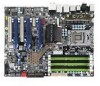
Figure 1 shows the motherboard and Figures 2 shows the back panel connectors. EVGA X58 SLI Motherboard The EVGA X58 SLI Motherboard with the Intel X58 and ICH10R chipset is a PCI Express, SLI-ready motherboard.
Figure 1 shows the motherboard and Figures 2 shows the back panel connectors. EVGA X58 SLI Motherboard The EVGA X58 SLI Motherboard with the Intel X58 and ICH10R chipset is a PCI Express, SLI-ready motherboard.

User Guide
Page 17
Remember to remove power from your computer by disconnecting the AC main source before removing or installing any equipment from/to the computer chassis. The topics covered in this section are: Preparing the motherboard Installing the CPU Installing the CPU fan Installing the memory Installing the motherboard Connecting cables Safety Instructions To reduce the risk of the motherboard. Hardware Installation This section will guide you through the installation of fire, electric shock, and injury, always follow basic safety precautions.
Remember to remove power from your computer by disconnecting the AC main source before removing or installing any equipment from/to the computer chassis. The topics covered in this section are: Preparing the motherboard Installing the CPU Installing the CPU fan Installing the memory Installing the motherboard Connecting cables Safety Instructions To reduce the risk of the motherboard. Hardware Installation This section will guide you through the installation of fire, electric shock, and injury, always follow basic safety precautions.

User Guide
Page 18
.... There is no CPU installed. It is a good idea to save the cover so that whenever you remove the CPU you hold it . Preparing the Motherboard Installing the CPU Be very careful when handling the CPU. Note: Remove the process from its protective cover, making sure you have a safe place to... there is a protective socket cover within the CPU socket to store it only by pushing down with light pressure to install the CPU onto the motherboard: Unhook the socket lever by the edges. Hold the processor only by the edges and do not touch the bottom of the load plate and...
.... There is no CPU installed. It is a good idea to save the cover so that whenever you remove the CPU you hold it . Preparing the Motherboard Installing the CPU Be very careful when handling the CPU. Note: Remove the process from its protective cover, making sure you have a safe place to... there is a protective socket cover within the CPU socket to store it only by pushing down with light pressure to install the CPU onto the motherboard: Unhook the socket lever by the edges. Hold the processor only by the edges and do not touch the bottom of the load plate and...
User Guide
Page 19
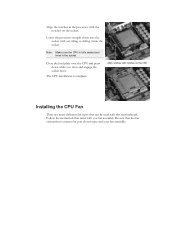
Align notches with notches on the socket. Be sure that came with this motherboard. The CPU installation is correct for your chassis type and your fan assembly. Lower the processor straight down while you fan assembly. Close the load ...
Align notches with notches on the socket. Be sure that came with this motherboard. The CPU installation is correct for your chassis type and your fan assembly. Lower the processor straight down while you fan assembly. Close the load ...
User Guide
Page 20
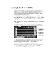
... 2 DIMM Slot 1 DIMM Slot 4 DIMM Slot 3 DIMM Slot 6 DIMM Slot 5 Use the following DIMM slots in this order: 5 and 6. Installing System Memory (DIMMs) Your new motherboard has six 240-pin slots for installing memory. (See Figure 1 on the memory DIMM to occupy the following procedure to the DIMM slot, and insert...
... 2 DIMM Slot 1 DIMM Slot 4 DIMM Slot 3 DIMM Slot 6 DIMM Slot 5 Use the following DIMM slots in this order: 5 and 6. Installing System Memory (DIMMs) Your new motherboard has six 240-pin slots for installing memory. (See Figure 1 on the memory DIMM to occupy the following procedure to the DIMM slot, and insert...
User Guide
Page 21
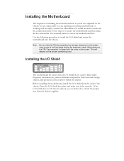
... shield does not fit into a system case depends on the chassis you are replacing an existing motherboard or working with the vents on the system case being used to secure the motherboard first. Also make all the connections prior to this step or to obtain the proper size from...and foreign objects, and promotes correct airflow within the chassis. If the I /O shield and secure the motherboard into place and make sure it would need to secure the motherboard and then make sure the CPU Fan assembly is normally easier to block radio frequency transmissions, protects internal ...
... shield does not fit into a system case depends on the chassis you are replacing an existing motherboard or working with the vents on the system case being used to secure the motherboard first. Also make all the connections prior to this step or to obtain the proper size from...and foreign objects, and promotes correct airflow within the chassis. If the I /O shield and secure the motherboard into place and make sure it would need to secure the motherboard and then make sure the CPU Fan assembly is normally easier to block radio frequency transmissions, protects internal ...

User Guide
Page 22
.... Ensure that you through all the necessary connections on the motherboard, it is aligned with the chassis vents according to secure the motherboard using a minimum of nine (9) spacers and screws. 1. Secure the motherboard with the studs/spacers. Align the mounting holes with a recommended... align with a mounting hole on the motherboard. If there are studs that stud to prevent the possibility of nine (9) screws. Carefully place the motherboard onto the stand off /spacers located inside the chassis. Securing the Motherboard into a System Case Most system cases ...
.... Ensure that you through all the necessary connections on the motherboard, it is aligned with the chassis vents according to secure the motherboard using a minimum of nine (9) spacers and screws. 1. Secure the motherboard with the studs/spacers. Align the mounting holes with a recommended... align with a mounting hole on the motherboard. If there are studs that stud to prevent the possibility of nine (9) screws. Carefully place the motherboard onto the stand off /spacers located inside the chassis. Securing the Motherboard into a System Case Most system cases ...

User Guide
Page 23
... 13 +3.3V 14 -12V 15 GND 16 PS_ON 17 GND 18 GND 19 GND 20 RSVD 21 +5V 22 +5V 23 +5V 24 GND PW1 Motherboard Connector Table 1. Firmly plug the power supply cable into the connector and make sure it is the main power supply connector located along the edge... of the board next to PW1 Figure 3. Make sure that the power supply cable and pins are properly aligned with the connector on the motherboard. USB 2.0 Expansion slots CMOS Clear Button 24-pin ATX Power (PW1) PW1 is secure.
... 13 +3.3V 14 -12V 15 GND 16 PS_ON 17 GND 18 GND 19 GND 20 RSVD 21 +5V 22 +5V 23 +5V 24 GND PW1 Motherboard Connector Table 1. Firmly plug the power supply cable into the connector and make sure it is the main power supply connector located along the edge... of the board next to PW1 Figure 3. Make sure that the power supply cable and pins are properly aligned with the connector on the motherboard. USB 2.0 Expansion slots CMOS Clear Button 24-pin ATX Power (PW1) PW1 is secure.
