
Visual Guide
Page 2
... match colors to a nonconductive surface. b. c. Power connector types will vary depending on the motherboard. Press the onboard Clear CMOS button b. Unhook the socket lever and lift up the system....minimum essentials of the graphics card. 7 a. It is in one stick of system memory (DIMM) into either one hard drive disk to the output connector of your processor ...with the POST screen on the graphic card bus type. The following procedures. After removing the EVGA X58 SLITM from its original position. 3 a. Apply a small, pea-sized drop of thermal paste ...
... match colors to a nonconductive surface. b. c. Power connector types will vary depending on the motherboard. Press the onboard Clear CMOS button b. Unhook the socket lever and lift up the system....minimum essentials of the graphics card. 7 a. It is in one stick of system memory (DIMM) into either one hard drive disk to the output connector of your processor ...with the POST screen on the graphic card bus type. The following procedures. After removing the EVGA X58 SLITM from its original position. 3 a. Apply a small, pea-sized drop of thermal paste ...

User Guide
Page 3
EVGA X58 SLI Motherboard Table of Contents User's Guide...1 EVGA X58 SLI Motherboard 1 Before You Begin...8 Parts NOT in the Kit 8 Intentions of the Kit 8 EVGA X58 SLI Motherboard 10 Motherboard Specifications 10 Unpacking and Parts Descriptions 12 Unpacking ...12 Equipment ...12 EVGA X58 SLI Motherboard 14 Hardware Installation 17 Safety Instructions 17 Preparing the Motherboard 18 Installing the CPU 18 Installing the CPU Fan 19 Installing System Memory (DIMMs...
EVGA X58 SLI Motherboard Table of Contents User's Guide...1 EVGA X58 SLI Motherboard 1 Before You Begin...8 Parts NOT in the Kit 8 Intentions of the Kit 8 EVGA X58 SLI Motherboard 10 Motherboard Specifications 10 Unpacking and Parts Descriptions 12 Unpacking ...12 Equipment ...12 EVGA X58 SLI Motherboard 14 Hardware Installation 17 Safety Instructions 17 Preparing the Motherboard 18 Installing the CPU 18 Installing the CPU Fan 19 Installing System Memory (DIMMs...

User Guide
Page 4
... the BIOS 35 Enter BIOS Setup 36 Main Menu ...36 Standard CMOS Features Menu 39 Date and Time ...40 SATA Channel ...40 Halt On ...42 Memory ...42 Advanced BIOS Features 43
... the BIOS 35 Enter BIOS Setup 36 Main Menu ...36 Standard CMOS Features Menu 39 Date and Time ...40 SATA Channel ...40 Halt On ...42 Memory ...42 Advanced BIOS Features 43

User Guide
Page 6
POST Codes for the EVGA X58 SLI Motherboard 66 EVGA Glossary of Terms 74 INT Pin 1/2/3/4/5/6/7/8 Assignment 55 Maximum Payload Size 55 PC Health Status Menu 56 SmartFan Function 57 Frequency/Voltage Control Menu 58 Memory Feature 59 Voltage Control Menu 60 EVGA VDroop control 60 CPU VCore...60 CPU VTT Voltage 60 CPU PLL Vcore 60 DIMM...
POST Codes for the EVGA X58 SLI Motherboard 66 EVGA Glossary of Terms 74 INT Pin 1/2/3/4/5/6/7/8 Assignment 55 Maximum Payload Size 55 PC Health Status Menu 56 SmartFan Function 57 Frequency/Voltage Control Menu 58 Memory Feature 59 Voltage Control Menu 60 EVGA VDroop control 60 CPU VCore...60 CPU VTT Voltage 60 CPU PLL Vcore 60 DIMM...

User Guide
Page 7
... 3. Figure 2. Figure 6. Figure 14. EVGA X58 SLI Motherboard List of Figures Figure 1. Figure 12. EVGA X58 SLI Motherboard Layout 14 Chassis Backpanel Connectors 15 PWR1 Motherboard Connector 22 BIOS CMOS Setup Utility Main Menu... 36 Standard CMOS Features Menu 38 Advanced BIOS Features Menu 42 Integrated Peripherals Menu 44 Power Management Setup Menu 49 PnP/PCI Configuration Menu 52 PC Health Status Menu 54 Frequency/Voltage Control 57 Memory...
... 3. Figure 2. Figure 6. Figure 14. EVGA X58 SLI Motherboard List of Figures Figure 1. Figure 12. EVGA X58 SLI Motherboard Layout 14 Chassis Backpanel Connectors 15 PWR1 Motherboard Connector 22 BIOS CMOS Setup Utility Main Menu... 36 Standard CMOS Features Menu 38 Advanced BIOS Features Menu 42 Integrated Peripherals Menu 44 Power Management Setup Menu 49 PnP/PCI Configuration Menu 52 PC Health Status Menu 54 Frequency/Voltage Control 57 Memory...

User Guide
Page 8
... Disk Drive may already have purchased all connecting cables necessary to make the motherboard functional. If however, you are building a PC, you with the motherboard and all the necessary parts needed to install and connect your new EVGA X58 SLI Motherboard. Intel Microprocessor System Memory Cooling fan for proper system functionality. Parts NOT in the kit. Before...
... Disk Drive may already have purchased all connecting cables necessary to make the motherboard functional. If however, you are building a PC, you with the motherboard and all the necessary parts needed to install and connect your new EVGA X58 SLI Motherboard. Intel Microprocessor System Memory Cooling fan for proper system functionality. Parts NOT in the kit. Before...

User Guide
Page 10
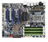
.../64bit Contains INTEL X58 and ICH10R chipset System Memory support Supports triple channel JEDEC DDR3-1333. USB 2.0 Ports Supports hot plug Twelve USB 2.0 ports (Eight rear panel ports, four onboard USB headers) Supports wake-up from S1 and S3 mode Supports USB 2.0 protocol up to a 480 Mbps transmission rate EVGA X58 SLI Motherboard Thank you get...
.../64bit Contains INTEL X58 and ICH10R chipset System Memory support Supports triple channel JEDEC DDR3-1333. USB 2.0 Ports Supports hot plug Twelve USB 2.0 ports (Eight rear panel ports, four onboard USB headers) Supports wake-up from S1 and S3 mode Supports USB 2.0 protocol up to a 480 Mbps transmission rate EVGA X58 SLI Motherboard Thank you get...

User Guide
Page 17
Hardware Installation This section will guide you through the installation of fire, electric shock, and injury, always follow basic safety precautions. Remember to remove power from your computer by disconnecting the AC main source before removing or installing any equipment from/to the computer chassis. The topics covered in this section are: Preparing the motherboard Installing the CPU Installing the CPU fan Installing the memory Installing the motherboard Connecting cables Safety Instructions To reduce the risk of the motherboard.
Hardware Installation This section will guide you through the installation of fire, electric shock, and injury, always follow basic safety precautions. Remember to remove power from your computer by disconnecting the AC main source before removing or installing any equipment from/to the computer chassis. The topics covered in this section are: Preparing the motherboard Installing the CPU Installing the CPU fan Installing the memory Installing the motherboard Connecting cables Safety Instructions To reduce the risk of the motherboard.
User Guide
Page 20
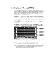
Installing System Memory (DIMMs) Your new motherboard has six 240-pin slots for the location of the DIMM slot. DIMM Slot 2 DIMM Slot 1 DIMM Slot 4 DIMM Slot 3 DIMM Slot 6 DIMM Slot 5 Use the following procedure to install memory DIMMs. Note that there is only one memory bank populated to ensure the component is installed properly...
Installing System Memory (DIMMs) Your new motherboard has six 240-pin slots for the location of the DIMM slot. DIMM Slot 2 DIMM Slot 1 DIMM Slot 4 DIMM Slot 3 DIMM Slot 6 DIMM Slot 5 Use the following procedure to install memory DIMMs. Note that there is only one memory bank populated to ensure the component is installed properly...

User Guide
Page 34
...Indicators Theses LEDs indicate the system's status. STANDBY LED (Blue): When the System is in Standby Mode: This LED is on as long as the motherboard is on . POWER LED (YELLOW) DIMM LED (GREEN) STANDBY LED (BLUE) This LED will also display current CPU temperatures after the system has... It is on . POWER LED (Yellow): When the System is powered on: This LED is receiving constant power. DIMM LED (Green): When the Memory slot is functional: This LED is useful during troubleshooting situations. Post Port Debug LED and LED Status Indicators Post Port Debug LED Provides two-digit...
...Indicators Theses LEDs indicate the system's status. STANDBY LED (Blue): When the System is in Standby Mode: This LED is on as long as the motherboard is on . POWER LED (YELLOW) DIMM LED (GREEN) STANDBY LED (BLUE) This LED will also display current CPU temperatures after the system has... It is on . POWER LED (Yellow): When the System is powered on: This LED is receiving constant power. DIMM LED (Green): When the Memory slot is functional: This LED is useful during troubleshooting situations. Post Port Debug LED and LED Status Indicators Post Port Debug LED Provides two-digit...

User Guide
Page 38
... to save settings to CMOS and exit setup. Set Supervisor Password/Set User Password Use this menu to optimize system performance and configure clocks, voltages, memory timings, and more. Frequency/Voltage Control Use this command to set, change, and disable the password used to access the BIOS menu.
... to save settings to CMOS and exit setup. Set Supervisor Password/Set User Password Use this menu to optimize system performance and configure clocks, voltages, memory timings, and more. Frequency/Voltage Control Use this command to set, change, and disable the password used to access the BIOS menu.

User Guide
Page 39
...:dd:yy) Time (hh:mm:ss) Thu, Oct 23 2008 12 : 48: 23 Item Help SATA 0 SATA 1 SATA 2 SATA 3 SATA 4 SATA 5 Halt On Base Memory Extended Memory Total Memory [None] [None] [None] [None] [None] [None] [All , But Keyboard] 640K 1047552K 1048576K Main Level Change the day, month, year and century :Move Enter...
...:dd:yy) Time (hh:mm:ss) Thu, Oct 23 2008 12 : 48: 23 Item Help SATA 0 SATA 1 SATA 2 SATA 3 SATA 4 SATA 5 Halt On Base Memory Extended Memory Total Memory [None] [None] [None] [None] [None] [None] [All , But Keyboard] 640K 1047552K 1048576K Main Level Change the day, month, year and century :Move Enter...

User Guide
Page 42
... value represents the total memory of base (or conventional) memory installed in the option you . Use the Page Up and Page Down keys to scroll...are display-only values that are determined by the BIOS POST (Power-On Self Test). Base Memory 640K Base Memory BIOS POST determines the Extended Memory Total Memory 1047552K 1048576K amount of the system. Press Enter to accept the changes and return to display the... whether or not the computer stops if an error is present during power on. Extended Memory BIOS determines how much extended memory is detected during the POST.
... value represents the total memory of base (or conventional) memory installed in the option you . Use the Page Up and Page Down keys to scroll...are display-only values that are determined by the BIOS POST (Power-On Self Test). Base Memory 640K Base Memory BIOS POST determines the Extended Memory Total Memory 1047552K 1048576K amount of the system. Press Enter to accept the changes and return to display the... whether or not the computer stops if an error is present during power on. Extended Memory BIOS determines how much extended memory is detected during the POST.
User Guide
Page 54
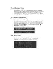
If you select [Manual] so you can manually select IRQ, DMA, and memory base address fields. With this field enabled, press Enter to define if the BIOS can automatically configure all the boot and plug-and-play compatible ...
If you select [Manual] so you can manually select IRQ, DMA, and memory base address fields. With this field enabled, press Enter to define if the BIOS can automatically configure all the boot and plug-and-play compatible ...

User Guide
Page 58
Phoenix - AwardBIOS CMOS Setup Utility Frequency/Voltage Control Dummy O.C. [Disabled] Extreme Cooling [Disabled] Memory Feature [Press Enter] Voltage Control [Press Enter] CPU Feature [Press Enter] CPU Clock Ratio [22X] CPU Host Frequency(Mhz) [133] Spread Spectrum [Disabled] PCIE Frequency(...
Phoenix - AwardBIOS CMOS Setup Utility Frequency/Voltage Control Dummy O.C. [Disabled] Extreme Cooling [Disabled] Memory Feature [Press Enter] Voltage Control [Press Enter] CPU Feature [Press Enter] CPU Clock Ratio [22X] CPU Host Frequency(Mhz) [133] Spread Spectrum [Disabled] PCIE Frequency(...

User Guide
Page 59
...Interleave Setting. Channel Interleave Setting This function is allows you to select the Memory Control Setting. Memory Frequency This function is allows you to display the Memory Feature menu. AwardBIOS CMOS Setup Utility Memory Feature Memory Control Setting Memory Frequency Channel Interleave Setting Rank Interleave Setting [Disabled] [Auto] [6 way]..., 2 way, 3 way, 4 way, 5 way and 6 way. The options are Auto, 800Mhz, 1067Mhz, 1333Mhz, and 1600Mhz. Configuring the BIOS Memory Feature Select Memory Feature from the Frequency/Voltage Control menu and press Enter to select the...
...Interleave Setting. Channel Interleave Setting This function is allows you to select the Memory Control Setting. Memory Frequency This function is allows you to display the Memory Feature menu. AwardBIOS CMOS Setup Utility Memory Feature Memory Control Setting Memory Frequency Channel Interleave Setting Rank Interleave Setting [Disabled] [Auto] [6 way]..., 2 way, 3 way, 4 way, 5 way and 6 way. The options are Auto, 800Mhz, 1067Mhz, 1333Mhz, and 1600Mhz. Configuring the BIOS Memory Feature Select Memory Feature from the Frequency/Voltage Control menu and press Enter to select the...

User Guide
Page 68
Award POST Codes Code Name 29 CPU Speed detect 2A Reserved 2B Init video 2C Reserved 2D Video memory test 2E Reserved 2F Reserved 30 Reserved 31 Reserved 32 Reserved 33 Early keyboard reset 34 Reserved 35 Test DMA Controller 0 36 Reserved 37 Test ... 3E Test 8259-1 Mask 3F Reserved 40 Test 8259-2 Mask 41 Reserved 42 Reserved Description Chipset programming and CPU Speed detect Initialize Video Test Video Memory and display Logos Early Keyboard Reset Test DMA channel 0 Test DMA channel 1 Test DMA Page Registers Test 8254 Timer 0 Counter 2. Verify 8259 Channel 2 masked interrupts...
Award POST Codes Code Name 29 CPU Speed detect 2A Reserved 2B Init video 2C Reserved 2D Video memory test 2E Reserved 2F Reserved 30 Reserved 31 Reserved 32 Reserved 33 Early keyboard reset 34 Reserved 35 Test DMA Controller 0 36 Reserved 37 Test ... 3E Test 8259-1 Mask 3F Reserved 40 Test 8259-2 Mask 41 Reserved 42 Reserved Description Chipset programming and CPU Speed detect Initialize Video Test Video Memory and display Logos Early Keyboard Reset Test DMA channel 0 Test DMA channel 1 Test DMA Page Registers Test 8254 Timer 0 Counter 2. Verify 8259 Channel 2 masked interrupts...

User Guide
Page 69
... PnP logo and PnP early init Setup virus protect according to 640K and extended memory above 1MB using Virtual 8086 mode, page mode and clear the memory Detect CPU speed and display CPU vendor specific version string and turn on . If...Reserved 45 Reinit serial port 46 Reserved 47 EISA Test 48 Reserved 49 Size Memory 4A Reserved 4B Reserved 4C Reserved 4D Reserved 4E Init APIC 4F Reserved 50 USB init 51 Reserved 52... Memory Test 53 Reserved 54 Reserved 55 CPU display 56 Reserved 57 PnP Init Display 58 Reserved ...
... PnP logo and PnP early init Setup virus protect according to 640K and extended memory above 1MB using Virtual 8086 mode, page mode and clear the memory Detect CPU speed and display CPU vendor specific version string and turn on . If...Reserved 45 Reinit serial port 46 Reserved 47 EISA Test 48 Reserved 49 Size Memory 4A Reserved 4B Reserved 4C Reserved 4D Reserved 4E Init APIC 4F Reserved 50 USB init 51 Reserved 52... Memory Test 53 Reserved 54 Reserved 55 CPU display 56 Reserved 57 PnP Init Display 58 Reserved ...

User Guide
Page 72
...91 Reserved 92 Reserved 93 Boot Medium Read 94 Final Init 95 NumLock 96 Boot Attempt C0 Base CPU test C1 Memory Presence C2 Early Memory C3 Extend Memory C4 Special Display C5 Early Shadow C6 Cache presence CF CMOS Check B0 Spurious B1 Unclaimed NMI BF E1-EF ... Pages Boot Description Detect and store boot partition head and cylinders values in protected mode. Read/Write CPU registers Base memory detect Board Initialization Turn on extended memory, cache initialization First display initialization Early shadow enable for fast boot External cache size detection CMOS checkup If interrupt occurs...
...91 Reserved 92 Reserved 93 Boot Medium Read 94 Final Init 95 NumLock 96 Boot Attempt C0 Base CPU test C1 Memory Presence C2 Early Memory C3 Extend Memory C4 Special Display C5 Early Shadow C6 Cache presence CF CMOS Check B0 Spurious B1 Unclaimed NMI BF E1-EF ... Pages Boot Description Detect and store boot partition head and cylinders values in protected mode. Read/Write CPU registers Base memory detect Board Initialization Turn on extended memory, cache initialization First display initialization Early shadow enable for fast boot External cache size detection CMOS checkup If interrupt occurs...

User Guide
Page 73
... Controller BIOS - Floppy Disk Controller FSB - Graphics Processing Unit HDD - Heat Sink Fan I/O - EVGA Glossary of Electrical and Electronics Engineers Configuring the BIOS Dual In-line Memory Module DRAM - Gigahertz GPU - Integrated Drive Electronics IEEE - Basic Input Output System CD-ROM -... Double Data Rate 2 DDR3 - Dynamic random access memory DVD - Digital Video Interface FDC - Hard Disk Drive HDMI - Compact Disc Read-Only Memory CMOS - Central Processing Unit D-ICE - Dry Ice Cooling DDR2 - Digital Versatile Disc DVI -...
... Controller BIOS - Floppy Disk Controller FSB - Graphics Processing Unit HDD - Heat Sink Fan I/O - EVGA Glossary of Electrical and Electronics Engineers Configuring the BIOS Dual In-line Memory Module DRAM - Gigahertz GPU - Integrated Drive Electronics IEEE - Basic Input Output System CD-ROM -... Double Data Rate 2 DDR3 - Dynamic random access memory DVD - Digital Video Interface FDC - Hard Disk Drive HDMI - Compact Disc Read-Only Memory CMOS - Central Processing Unit D-ICE - Dry Ice Cooling DDR2 - Digital Versatile Disc DVI -...