User Manual
Page 2
User Guide EVGA nForce 750i SLI Motherboard
User Guide EVGA nForce 750i SLI Motherboard
User Manual
Page 7
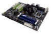
...go through the installation instructions, we are going to make the motherboard functional. Parts NOT in a PC case, you will not need a minimum of the cables provided in an SLI configuration, you can have purchased the necessary parts. If you ...must be purchased separately to require more power. Graphics Card This motherboard supports 2-way SLI with the motherboard and all the hardware necessary to install the motherboard into a PC case. nForce 750i SLI Motherboard Before You Begin... As you are going to require for your new EVGA nForce® 750i SLI motherboard.
...go through the installation instructions, we are going to make the motherboard functional. Parts NOT in a PC case, you will not need a minimum of the cables provided in an SLI configuration, you can have purchased the necessary parts. If you ...must be purchased separately to require more power. Graphics Card This motherboard supports 2-way SLI with the motherboard and all the hardware necessary to install the motherboard into a PC case. nForce 750i SLI Motherboard Before You Begin... As you are going to require for your new EVGA nForce® 750i SLI motherboard.
User Manual
Page 8
...1394a ports (one rear panel port, one onboard header) with two SLI-Ready NVIDIA GeForce graphics cards, you for enhanced system performance. EVGA EVGA nForce 750i Motherboard Thank you get innovative NVIDIA SLI Technology for buying the EVGA NFORCE 750i SLI Motherboard. This motherboard offers the tools and performance PC users' demand. When combined with... 2 Duo, Pentium EE, Pentium D, Pentium Operating systems: Supports Windows XP 32bit/64bit and Windows Vista 32bit/64bit Contains NVIDIA nForce 750i SLI MCP and SPP System Memory support Supports dual channel JEDEC DDR2-800 memory.
...1394a ports (one rear panel port, one onboard header) with two SLI-Ready NVIDIA GeForce graphics cards, you for enhanced system performance. EVGA EVGA nForce 750i Motherboard Thank you get innovative NVIDIA SLI Technology for buying the EVGA NFORCE 750i SLI Motherboard. This motherboard offers the tools and performance PC users' demand. When combined with... 2 Duo, Pentium EE, Pentium D, Pentium Operating systems: Supports Windows XP 32bit/64bit and Windows Vista 32bit/64bit Contains NVIDIA nForce 750i SLI MCP and SPP System Memory support Supports dual channel JEDEC DDR2-800 memory.

User Manual
Page 9
off) Expansion Slots Three PCI slots One PCI Express x1 slot Two PCI Express x16 Graphics slot compliant with PCI Express 2.0 nForce 750i SLI Motherboard Onboard Audio Azalia High-Definition audio Supports 8-channel audio Supports S/PDIF output Supports Jack-Sensing function Green Function Supports ACPI (Advanced Configuration and Power Interface) Supports S0 (normal), S1 (power on suspend), S3 (suspend to RAM), S4 (Suspend to disk depends on OS), and S5 (soft -
off) Expansion Slots Three PCI slots One PCI Express x1 slot Two PCI Express x16 Graphics slot compliant with PCI Express 2.0 nForce 750i SLI Motherboard Onboard Audio Azalia High-Definition audio Supports 8-channel audio Supports S/PDIF output Supports Jack-Sensing function Green Function Supports ACPI (Advanced Configuration and Power Interface) Supports S0 (normal), S1 (power on suspend), S3 (suspend to RAM), S4 (Suspend to disk depends on OS), and S5 (soft -
User Manual
Page 10
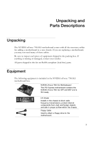
... The following equipment is missing or damaged, contact your reseller. NVIDIA nForce 750i SLI Motherboard This PCI Express motherboard contains the NVIDIA nForce 750i SLI SPP and MCP and is SLI-ready. Unpacking and Parts Descriptions Unpacking The NVIDIA nForce 750i SLI motherboard comes with all the necessary cables for adding a motherboard to block radio frequency transmissions, protect internet components from dust and foreign...
... The following equipment is missing or damaged, contact your reseller. NVIDIA nForce 750i SLI Motherboard This PCI Express motherboard contains the NVIDIA nForce 750i SLI SPP and MCP and is SLI-ready. Unpacking and Parts Descriptions Unpacking The NVIDIA nForce 750i SLI motherboard comes with all the necessary cables for adding a motherboard to block radio frequency transmissions, protect internet components from dust and foreign...

User Manual
Page 13
...PCI slots 25. PCI Express x16 slots 26.1394a connector 27. Chipset fan connector 1 7 2 3 4 5 6 4 4 Figure 2. EVGA nForce 750i SLI Backpanel connectors 1. SPDIF output 6. Front panel connector 14. SPDIF connector 24. Post port 10. Auxiliary fan connector 17. Power button 19.... Out Pink Mic In Mic In Orange Black Rear Speaker Out Grey 7. CPU 775 Socket 2. Serial-ATA (SATA) connectors 9. nForce 750i SLI Motherboard 1. DDR2 DIMM slots 0 - 3 4. 24-pin ATX power connector 5. IDE connector 6. Chassis fan2 connector 7. Serial connector ...
...PCI slots 25. PCI Express x16 slots 26.1394a connector 27. Chipset fan connector 1 7 2 3 4 5 6 4 4 Figure 2. EVGA nForce 750i SLI Backpanel connectors 1. SPDIF output 6. Front panel connector 14. SPDIF connector 24. Post port 10. Auxiliary fan connector 17. Power button 19.... Out Pink Mic In Mic In Orange Black Rear Speaker Out Grey 7. CPU 775 Socket 2. Serial-ATA (SATA) connectors 9. nForce 750i SLI Motherboard 1. DDR2 DIMM slots 0 - 3 4. 24-pin ATX power connector 5. IDE connector 6. Chassis fan2 connector 7. Serial connector ...

User Manual
Page 15
nForce 750i SLI Motherboard Installing the CPU Be very careful when handling the CPU. Hold the processor only by the edges. Lift the load plate. Follow the instruction that the fan orientation is a good idea to install the CPU onto the motherboard. 1. Remove the processor from its protective cover, making ... or break any pins on the CPU 7. Unhook the socket lever by pushing down while you hold it into the socket with this motherboard. Close the load plate over the CPU and press down and away from the load plate. 4. Remove the protective socket cover from the...
nForce 750i SLI Motherboard Installing the CPU Be very careful when handling the CPU. Hold the processor only by the edges. Lift the load plate. Follow the instruction that the fan orientation is a good idea to install the CPU onto the motherboard. 1. Remove the processor from its protective cover, making ... or break any pins on the CPU 7. Unhook the socket lever by pushing down while you hold it into the socket with this motherboard. Close the load plate over the CPU and press down and away from the load plate. 4. Remove the protective socket cover from the...

User Manual
Page 17
... expansion cards. It is aligned with the vents on the covers. If there are replacing an existing motherboard or working with a minimum of eight-to-ten screws. nForce 750i SLI Motherboard Installing the Motherboard The sequence of installing the motherboard into the chassis depends on the chassis you are using a minimum of the chassis. Use the following...
... expansion cards. It is aligned with the vents on the covers. If there are replacing an existing motherboard or working with a minimum of eight-to-ten screws. nForce 750i SLI Motherboard Installing the Motherboard The sequence of installing the motherboard into the chassis depends on the chassis you are using a minimum of the chassis. Use the following...

User Manual
Page 19
... is used to provide power to the CPU. Make sure that the power supply cable and pins are properly aligned with the connector on the motherboard. nForce 750i SLI Motherboard Power Connections 24-pin ATX Power PWR1 is the main power supply connector located along the edge of the board next to the connector and...
... is used to provide power to the CPU. Make sure that the power supply cable and pins are properly aligned with the connector on the motherboard. nForce 750i SLI Motherboard Power Connections 24-pin ATX Power PWR1 is the main power supply connector located along the edge of the board next to the connector and...

User Manual
Page 21
v Pin Assignments Connector SATA B1 SATA B0 SATA A0 (bottom) SATA A1 (top) Pin Signal 1 GND 2 TX+ 3 TX- 4 GND 5 RX+ 6 RX- 7 GND Connecting Floppy Disk Drive The motherboard supports a standard 360K, 720K, 1.2M, 1.44m, and a 2.88M floppy disk drive (FDD). v Pin Assignments Connector Pin Signal Pin Signal 1 ... 0,RAID 1, RAID 5, RAID 0+1 and JBOD configurations. The current Serial ATA II interface allows up to the motherboard. nForce 750i SLI Motherboard Connecting Serial ATA Cables The Serial ATA II connector is used to connect the Serial ATA II device to 300MB/s...
v Pin Assignments Connector SATA B1 SATA B0 SATA A0 (bottom) SATA A1 (top) Pin Signal 1 GND 2 TX+ 3 TX- 4 GND 5 RX+ 6 RX- 7 GND Connecting Floppy Disk Drive The motherboard supports a standard 360K, 720K, 1.2M, 1.44m, and a 2.88M floppy disk drive (FDD). v Pin Assignments Connector Pin Signal Pin Signal 1 ... 0,RAID 1, RAID 5, RAID 0+1 and JBOD configurations. The current Serial ATA II interface allows up to the motherboard. nForce 750i SLI Motherboard Connecting Serial ATA Cables The Serial ATA II connector is used to connect the Serial ATA II device to 300MB/s...
User Manual
Page 23
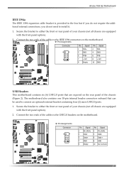
...Assignments Connector Pin Signal 1 TPA+ 3 GND 5 TPB+ 7 +12V 9 Empty Pin Signal 2 TPA4 GND 6 TPB8 +12V 10 GND USB Headers This motherboard contains six (6) USB 2.0 ports that can be used to either the front or rear panel of your chassis (not all chassis are equipped with the ... one 10-pin internal header connectors onboard that are equipped with the front panel option). 2. Secure the bracket to install it. 1. nForce 750i SLI Motherboard IEEE 1394a The IEEE 1394 expansion cable bracket is provided in the box but if you do not require the additional external connections, you...
...Assignments Connector Pin Signal 1 TPA+ 3 GND 5 TPB+ 7 +12V 9 Empty Pin Signal 2 TPA4 GND 6 TPB8 +12V 10 GND USB Headers This motherboard contains six (6) USB 2.0 ports that can be used to either the front or rear panel of your chassis (not all chassis are equipped with the ... one 10-pin internal header connectors onboard that are equipped with the front panel option). 2. Secure the bracket to install it. 1. nForce 750i SLI Motherboard IEEE 1394a The IEEE 1394 expansion cable bracket is provided in the box but if you do not require the additional external connections, you...

User Manual
Page 25
... Assignments Connector Pin Signal 1 CONTROL 2 SENSE 3 +12V 4 GND Connector Pin Signal 1 SENSE 2 +12V 3 +12V nForce 750i SLI Motherboard Fan Connections There are six fan connections on the motherboard connector. The fans are four more fan connectors on the motherboard. CPU FAN NFORCE FAN CPU FAN: Connect the CPU fan to draw heat from the MCP. Connect a 3-pin...
... Assignments Connector Pin Signal 1 CONTROL 2 SENSE 3 +12V 4 GND Connector Pin Signal 1 SENSE 2 +12V 3 +12V nForce 750i SLI Motherboard Fan Connections There are six fan connections on the motherboard connector. The fans are four more fan connectors on the motherboard. CPU FAN NFORCE FAN CPU FAN: Connect the CPU fan to draw heat from the MCP. Connect a 3-pin...

User Manual
Page 26
...PCI Express x1 slot that is not seated properly, it is purchased separately from the motherboard). When installing a PCI Express x16 card, be sure that comply with x8 bandwith using NVIDIA's SLI technology. The x1 slot provides 250 MB/sec bandwidth. PCI Slots The three PCI slots...locks the card into the "PCIE X16_1" VGA slot. (labeled on the top of this motherboard, go to link the cards together. (The kit is fully seated. EVGA Expansion Slots The EVGA nForce 750i SLI motherboard contains six expansion slots, three PCI Express slots and three PCI slots. The design of both...
...PCI Express x1 slot that is not seated properly, it is purchased separately from the motherboard). When installing a PCI Express x16 card, be sure that comply with x8 bandwith using NVIDIA's SLI technology. The x1 slot provides 250 MB/sec bandwidth. PCI Slots The three PCI slots...locks the card into the "PCIE X16_1" VGA slot. (labeled on the top of this motherboard, go to link the cards together. (The kit is fully seated. EVGA Expansion Slots The EVGA nForce 750i SLI motherboard contains six expansion slots, three PCI Express slots and three PCI slots. The design of both...

User Manual
Page 27
The CMOS can be cleared by press the CMOS button. nForce 750i SLI Motherboard Onboard Buttons These onboard buttons include RESET, POWER and CMOS , lets you turn on/off the system easily, and convenient for clear CMOS RESET and ... Button Post Port Debug LED Provides two-digit POST code to show why the system fail to store all the set parameters. CMOS Button: The motherboard uses the CMOS RAM to boot. Allows quick and easy optimization.
The CMOS can be cleared by press the CMOS button. nForce 750i SLI Motherboard Onboard Buttons These onboard buttons include RESET, POWER and CMOS , lets you turn on/off the system easily, and convenient for clear CMOS RESET and ... Button Post Port Debug LED Provides two-digit POST code to show why the system fail to store all the set parameters. CMOS Button: The motherboard uses the CMOS RAM to boot. Allows quick and easy optimization.

User Manual
Page 28
... do not change the default BIOS settings. This section includes the following message briefly displays at the bottom of the BIOS parameters are also provided. nForce 750i SLI Motherboard Configuring the BIOS This section discusses how to change BIOS settings. 1. Press the Del key when the following information: Enter BIOS Setup Main Menu Standard...
... do not change the default BIOS settings. This section includes the following message briefly displays at the bottom of the BIOS parameters are also provided. nForce 750i SLI Motherboard Configuring the BIOS This section discusses how to change BIOS settings. 1. Press the Del key when the following information: Enter BIOS Setup Main Menu Standard...
User Manual
Page 30
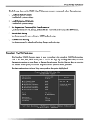
... Setup Utility Standard CMOS Features Date (mm:dd:yy) Time (hh:mm:ss) IDE Channel 0 Master IDE Channel 0 Slave SATA Channel 1 (A0) Master SATA Channel 2 (A1) Master SATA Channel 3 (B0) Master SATA Channel 4 (C1) Master Sat, Jul 01 2006 12 : 48: 23 [None] [None] [None] [None] [None] [None] Item Help Main.... Phoenix - Use the Page Up and Page Down keys to scroll through the options or press Enter to abandon all setting changes and exit setup. nForce 750i SLI Motherboard The following items on . Load Optimized Defaults Load default system settings.
... Setup Utility Standard CMOS Features Date (mm:dd:yy) Time (hh:mm:ss) IDE Channel 0 Master IDE Channel 0 Slave SATA Channel 1 (A0) Master SATA Channel 2 (A1) Master SATA Channel 3 (B0) Master SATA Channel 4 (C1) Master Sat, Jul 01 2006 12 : 48: 23 [None] [None] [None] [None] [None] [None] Item Help Main.... Phoenix - Use the Page Up and Page Down keys to scroll through the options or press Enter to abandon all setting changes and exit setup. nForce 750i SLI Motherboard The following items on . Load Optimized Defaults Load default system settings.

User Manual
Page 32
nForce 750i SLI Motherboard the + or - To go back to the previous menu, press Esc. Select Off to access the CMOS Setup screen and when the system boots. Select ...
nForce 750i SLI Motherboard the + or - To go back to the previous menu, press Esc. Select Off to access the CMOS Setup screen and when the system boots. Select ...

User Manual
Page 34
... Master and Slave UDMA or set to [Auto]. Select from the CMOS Setup Utility menu and press Enter to display the IDE Function Setup menu. nForce 750i SLI Motherboard Integrated Peripherals Menu Select Integrated Peripherals from Auto, or Mode 1 through Mode 4. Phoenix -
... Master and Slave UDMA or set to [Auto]. Select from the CMOS Setup Utility menu and press Enter to display the IDE Function Setup menu. nForce 750i SLI Motherboard Integrated Peripherals Menu Select Integrated Peripherals from Auto, or Mode 1 through Mode 4. Phoenix -
User Manual
Page 36
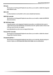
... LAN Use these functions to set the MAC LAN to automatically detect the optimal number of block read/ writes per sector the drive can support. nForce 750i SLI Motherboard HD Audio This function on the Integrated Peripherals menu allows you to enable or disable the onboard Floppy Disk Controller function.
... LAN Use these functions to set the MAC LAN to automatically detect the optimal number of block read/ writes per sector the drive can support. nForce 750i SLI Motherboard HD Audio This function on the Integrated Peripherals menu allows you to enable or disable the onboard Floppy Disk Controller function.
User Manual
Page 38
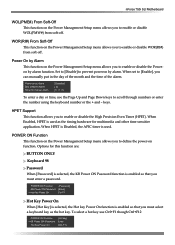
... you to enable or disable the Poweron by Alarm This function on the Power Management Setup menu allows you to define the power-on function. nForce 750i SLI Motherboard WOL(PME#) From Soft-Off This function on the Power Management Setup menu allows you to enable or disable WOL(PMW#) from soft-off . Power...
... you to enable or disable the Poweron by Alarm This function on the Power Management Setup menu allows you to define the power-on function. nForce 750i SLI Motherboard WOL(PME#) From Soft-Off This function on the Power Management Setup menu allows you to enable or disable WOL(PMW#) from soft-off . Power...


