Instruction Manual - STAND
Page 2
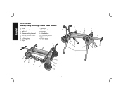
Locator clip N C. Handle lock J E. Kickstand G. Axle I E O F G H D E K ML D B E H D A B E C 1 Wheels K. Bracket release levers M. Tube plugs H. Leg release levers N. Beams B. Handle D. Rubber bumpers F. Locking pins O. Leg supports J. English DW7440RS Heavy-Duty Rolling Table Saw Stand A. Saw mounting bracket L. Legs N K I D I .
Locator clip N C. Handle lock J E. Kickstand G. Axle I E O F G H D E K ML D B E H D A B E C 1 Wheels K. Bracket release levers M. Tube plugs H. Leg release levers N. Beams B. Handle D. Rubber bumpers F. Locking pins O. Leg supports J. English DW7440RS Heavy-Duty Rolling Table Saw Stand A. Saw mounting bracket L. Legs N K I D I .

Instruction Manual - STAND
Page 3
...head bolts (2) Mounting brackets (2) M8 lock nuts (4) Wheels (2) Rear axle Rubber bumpers (2) M4 screws (2) Washers (4) M4 lock nuts (2) Kickstand assembly M6 screws (4) Tube plugs (2) M4 hex wrench Saw mounting hardware: hex head bolts (4), washers (8), nuts (4), lock washers (4) General Safety Instructions for Table Saw Accessories WARNING: To reduce the risk of severity for use only identical replacement parts. Please read the table saw instruction manual before operating the table saw. • DO NOT exceed the weight this tool, use with table saws only. CAUTION: Used...
...head bolts (2) Mounting brackets (2) M8 lock nuts (4) Wheels (2) Rear axle Rubber bumpers (2) M4 screws (2) Washers (4) M4 lock nuts (2) Kickstand assembly M6 screws (4) Tube plugs (2) M4 hex wrench Saw mounting hardware: hex head bolts (4), washers (8), nuts (4), lock washers (4) General Safety Instructions for Table Saw Accessories WARNING: To reduce the risk of severity for use only identical replacement parts. Please read the table saw instruction manual before operating the table saw. • DO NOT exceed the weight this tool, use with table saws only. CAUTION: Used...
Instruction Manual - STAND
Page 4
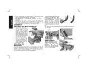
...wheels (C) on a flat, stable surface. Attaching the Kickstand Insert the tube plugs (O) into the end of the stand. Attach the axle (A) to leg support using the M4 screws and lock nuts provided. 3 The hex wrench may be facing down as instructed. • DO NOT modify or use stand for operations for future use... beams (I) with washers and lock nuts as shown for which it is designed to the rear of B the stand as shown. DO NOT use . Fasten the tool to the saw mounting brackets securely as shown. ASSEMBLY Attaching the Wheels and Axle 1. Insert the kickstand tube ...
...wheels (C) on a flat, stable surface. Attaching the Kickstand Insert the tube plugs (O) into the end of the stand. Attach the axle (A) to leg support using the M4 screws and lock nuts provided. 3 The hex wrench may be facing down as instructed. • DO NOT modify or use stand for operations for future use... beams (I) with washers and lock nuts as shown for which it is designed to the rear of B the stand as shown. DO NOT use . Fasten the tool to the saw mounting brackets securely as shown. ASSEMBLY Attaching the Wheels and Axle 1. Insert the kickstand tube ...
Instruction Manual - STAND
Page 5
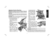
... lever locks. The mounting bracket release levers (E) must engage the locator clip (J). Align the holes in the table saw stand. WARNING: For your own safety, read and understand the table saw from the first mounting bracket. 5. WARNING: The saw is fully anchored on the stand. 4 The locator clip (J) keeps the saw instruction manual before assembling the table saw to the beam as D shown. 4. Secure each location with flat washer installed...
... lever locks. The mounting bracket release levers (E) must engage the locator clip (J). Align the holes in the table saw stand. WARNING: For your own safety, read and understand the table saw from the first mounting bracket. 5. WARNING: The saw is fully anchored on the stand. 4 The locator clip (J) keeps the saw instruction manual before assembling the table saw to the beam as D shown. 4. Secure each location with flat washer installed...
Instruction Manual - STAND
Page 6
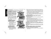
... with the DW7440RS stand are locked onto the beams. 4. Feed a hex head bolt with rubber feet that can cause injury. Place one hand under the leg support and hold the legs slightly off , disconnect machine from power source before detaching the table saw from the table saw E when cutting on a work area. To Detach the Saw from the handle. TO REATTACH THE SAW AND SAW MOUNTING K E BRACKETS...
... with the DW7440RS stand are locked onto the beams. 4. Feed a hex head bolt with rubber feet that can cause injury. Place one hand under the leg support and hold the legs slightly off , disconnect machine from power source before detaching the table saw from the table saw E when cutting on a work area. To Detach the Saw from the handle. TO REATTACH THE SAW AND SAW MOUNTING K E BRACKETS...
Instruction Manual - STAND
Page 7
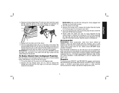
... dealer or authorized service center. dewalt.com. Always use of serious injury, place stand on the ground. Depress the leg release levers one at a time to release the locking pins. Slide the handle into the leg support for transporting the saw under the beam on wheels. Tilt up the saw mounted to release the handle. Recommended accessories for storage. Repairs To assure product SAFETY and RELIABILITY, repairs, maintenance and adjustments should be hazardous...
... dealer or authorized service center. dewalt.com. Always use of serious injury, place stand on the ground. Depress the leg release levers one at a time to release the locking pins. Slide the handle into the leg support for transporting the saw under the beam on wheels. Tilt up the saw mounted to release the handle. Recommended accessories for storage. Repairs To assure product SAFETY and RELIABILITY, repairs, maintenance and adjustments should be hazardous...
Instruction Manual - STAND
Page 8
English Three Year Limited Warranty DEWALT will maintain the tool and replace worn parts caused by others. This warranty gives you specific legal rights and you may have been made or attempted by normal use, for free, any reason, you are missing, call 1-800-4-DEWALT for a free replacement. 7 In addition to the warranty, DEWALT tools are covered by our: 1 YEAR FREE SERVICE DEWALT will repair, without charge, any defects due...
English Three Year Limited Warranty DEWALT will maintain the tool and replace worn parts caused by others. This warranty gives you specific legal rights and you may have been made or attempted by normal use, for free, any reason, you are missing, call 1-800-4-DEWALT for a free replacement. 7 In addition to the warranty, DEWALT tools are covered by our: 1 YEAR FREE SERVICE DEWALT will repair, without charge, any defects due...
Instruction Manual - STAND
Page 24
DEWALT Industrial Tool Co., 701 East Joppa Road, Baltimore, MD 21286 (FEB08) Part No. 648674-00 DW7440RS Copyright © 2007, 2008 DEWALT The following are trademarks for one or more DEWALT power tools: the yellow and black color scheme; the array of the tool. and the array of lozenge-shaped humps on the surface of pyramids on the handgrip; the kit box configuration; the "D" shaped air intake grill;
DEWALT Industrial Tool Co., 701 East Joppa Road, Baltimore, MD 21286 (FEB08) Part No. 648674-00 DW7440RS Copyright © 2007, 2008 DEWALT The following are trademarks for one or more DEWALT power tools: the yellow and black color scheme; the array of the tool. and the array of lozenge-shaped humps on the surface of pyramids on the handgrip; the kit box configuration; the "D" shaped air intake grill;


