
Instruction Manual
Page 3
... surface. Keep your tool may result in the presence of staring into the laser beam. Class IIIa Laser .....laser warning symbol 1 SAVE THESE INSTRUCTIONS Safety Instructions for your nearest DEWALT service center call 1-800-4-DEWALT (1-800-433-9258) or go to http://www.dewalt.com on the Internet. • Do not use . Serious eye injury may...
... surface. Keep your tool may result in the presence of staring into the laser beam. Class IIIa Laser .....laser warning symbol 1 SAVE THESE INSTRUCTIONS Safety Instructions for your nearest DEWALT service center call 1-800-4-DEWALT (1-800-433-9258) or go to http://www.dewalt.com on the Internet. • Do not use . Serious eye injury may...

Instruction Manual
Page 4
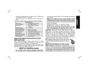
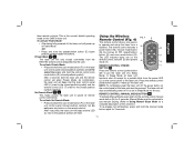
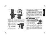
... with Part 15 of the FCC Rules. the Center for a Class B digital device, pursuant to radio communications. AVOID EXPOSURE: LASER RADIATION IS EMITTED FROM THIS APERTURES. These devices comply with the applicable requirement of title 21 of the Code of Federal Regulations set... forth by one or more of Health, Education, and Welfare; English FIG. 1 • For your laser (Fig. 1). These limits are on , the user is subject to the following two conditions: (1) this device must accept any interference received, including ...
... with Part 15 of the FCC Rules. the Center for a Class B digital device, pursuant to radio communications. AVOID EXPOSURE: LASER RADIATION IS EMITTED FROM THIS APERTURES. These devices comply with the applicable requirement of title 21 of the Code of Federal Regulations set... forth by one or more of Health, Education, and Welfare; English FIG. 1 • For your laser (Fig. 1). These limits are on , the user is subject to the following two conditions: (1) this device must accept any interference received, including ...
Instruction Manual
Page 5
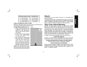
These Class B digital devices comply with Canadian ICES-003. English • Connect the equipment into an outlet on a circuit differentfrom that which the receiver is connected. • Consult the dealer or an experienced radio/TV technician for help. SPECIFICATIONS Light Source Semiconductor laser diode Laser Wavelength 630 - 680 nm Visible Laser Power
These Class B digital devices comply with Canadian ICES-003. English • Connect the equipment into an outlet on a circuit differentfrom that which the receiver is connected. • Consult the dealer or an experienced radio/TV technician for help. SPECIFICATIONS Light Source Semiconductor laser diode Laser Wavelength 630 - 680 nm Visible Laser Power
Instruction Manual
Page 10
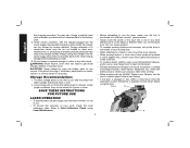
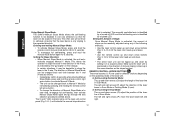
...If you mark different parts of the beam at different times you desire with the DEWALT Digital Laser Detector, set up the laser in use a Laser Target Card to the fastest setting. • If the laser is no adverse affect on a relatively smooth, secure surface. • Always mark ...immerse charger in the cavity. Storage Recommendations 1. SAVE THESE INSTRUCTIONS FOR FUTURE USE • Before attempting to a tripod or wall, mount the laser securely. • When working indoors, a slow rotary head speed will produce a visibly brighter line, a faster rotary head speed will not ...
...If you mark different parts of the beam at different times you desire with the DEWALT Digital Laser Detector, set up the laser in use a Laser Target Card to the fastest setting. • If the laser is no adverse affect on a relatively smooth, secure surface. • Always mark ...immerse charger in the cavity. Storage Recommendations 1. SAVE THESE INSTRUCTIONS FOR FUTURE USE • Before attempting to a tripod or wall, mount the laser securely. • When working indoors, a slow rotary head speed will produce a visibly brighter line, a faster rotary head speed will not ...

Instruction Manual
Page 11
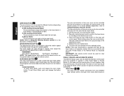
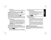
... power off except for 8 hours. Insert the battery pack (C). Slide the battery pack in the plumb mode. The arrows control the movement of the laser unit must be illuminated. Insert the fully charged battery pack. FIG. 3 LD I ), X-axis leveling (J), Y-axis leveling (K) and remote control private...button (E), the scan mode button (F), and two arrows (G, H). Remove the battery pack. 3. If the laser is level. NOTE: Press the remote control power button to put the laser unit into the charger as described in Sleep Mode for a periodic blink from the power LED on the ...
... power off except for 8 hours. Insert the battery pack (C). Slide the battery pack in the plumb mode. The arrows control the movement of the laser unit must be illuminated. Insert the fully charged battery pack. FIG. 3 LD I ), X-axis leveling (J), Y-axis leveling (K) and remote control private...button (E), the scan mode button (F), and two arrows (G, H). Remove the battery pack. 3. If the laser is level. NOTE: Press the remote control power button to put the laser unit into the charger as described in Sleep Mode for a periodic blink from the power LED on the ...
Instruction Manual
Page 12
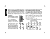
...preset speeds. The size and direction of the scan zone can receive commands from any DEWALT laser remote control, and even from some other brands of the desired scan zone. 4. Manually rotate the laser head to position the laser beam at 0 rpm (pointer mode). 2. While holding down the scan mode button,...adjust the rotation speed of the scan zone can also be controlled manually with the arrow buttons on the laser unit control panel. The size and direction of the laser beam through 4 speeds, then repeat the sequence as the speed/rotation button is much brighter and more detailed...
...preset speeds. The size and direction of the scan zone can receive commands from any DEWALT laser remote control, and even from some other brands of the desired scan zone. 4. Manually rotate the laser head to position the laser beam at 0 rpm (pointer mode). 2. While holding down the scan mode button,...adjust the rotation speed of the scan zone can also be controlled manually with the arrow buttons on the laser unit control panel. The size and direction of the laser beam through 4 speeds, then repeat the sequence as the speed/rotation button is much brighter and more detailed...
Instruction Manual
Page 13
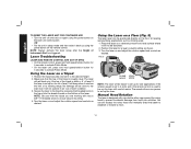
... the remote control scan mode button (R) (closed padlock symbol), but do not press any button on the remote control. NOTE: To completely power the laser unit off if it is the normal, default operating mode for 3 seconds. 11 This is left in Public Mode. Using the Wireless FIG. 4 ...scan mode button (R). In Sleep Mode all remote control commands. To activate Private Mode: • Press and hold the scan mode button (F) on the laser unit control panel (closed padlock symbol) and at the same time press and hold the scan mode button (F) on the control panel of the...
... the remote control scan mode button (R) (closed padlock symbol), but do not press any button on the remote control. NOTE: To completely power the laser unit off if it is the normal, default operating mode for 3 seconds. 11 This is left in Public Mode. Using the Wireless FIG. 4 ...scan mode button (R). In Sleep Mode all remote control commands. To activate Private Mode: • Press and hold the scan mode button (F) on the laser unit control panel (closed padlock symbol) and at the same time press and hold the scan mode button (F) on the control panel of the...
Instruction Manual
Page 14
...manual slope direction that is identified by immediately pressing and holding the remote control left arrow button. • To change the direction of the laser line in the X-axis. Entering and exiting Manual Slope Mode: • To activate Manual Slope Mode, press and hold the remote control ...-off LED, and the self-leveling axis is selected. In Self-Leveling Vertical Mode: The up and down arrows (O) adjust the length of the laser beam in the same direction as follows: • Immediately (within 5 seconds) after entering Manual Slope Mode, press and hold the manual mode button...
...manual slope direction that is identified by immediately pressing and holding the remote control left arrow button. • To change the direction of the laser line in the X-axis. Entering and exiting Manual Slope Mode: • To activate Manual Slope Mode, press and hold the remote control ...-off LED, and the self-leveling axis is selected. In Self-Leveling Vertical Mode: The up and down arrows (O) adjust the length of the laser beam in the same direction as follows: • Immediately (within 5 seconds) after entering Manual Slope Mode, press and hold the manual mode button...
Instruction Manual
Page 15
... and more detailed explanation, refer to the same mode. Private Mode The remote control sends signals that can only be received by multiple laser units as well as other models of Instrument Alert The DW079 has a built-in alarm feature that can be used for the DW0794 .... REMOTE CONTROL: SPEED/ROTATION BUTTON The speed/rotation button (Q) is disturbed after the unit has self-leveled. As confirmation, the laser unit will beep and the laser unit control panel LED (L) (next to the closed padlock symbol) and the remote control LED (T) (next to operate in full rotation mode....
... and more detailed explanation, refer to the same mode. Private Mode The remote control sends signals that can only be received by multiple laser units as well as other models of Instrument Alert The DW079 has a built-in alarm feature that can be used for the DW0794 .... REMOTE CONTROL: SPEED/ROTATION BUTTON The speed/rotation button (Q) is disturbed after the unit has self-leveled. As confirmation, the laser unit will beep and the laser unit control panel LED (L) (next to the closed padlock symbol) and the remote control LED (T) (next to operate in full rotation mode....
Instruction Manual
Page 16
... off and back on again using the power button on the remote control. OR • Put the unit in an "out of level. Using the Laser on and adjust the rotation speed and controls as framing walls. 1. Make sure that the tripod you are working with has a 5/8"-11 threaded screw to... of the tripod is set up using the power button on the bottom of Instrument Alert has triggered. NOTE: Always recheck the laser setup after the Height of the laser. No damage will self-level only if the top of the tripod is designed with control marks. You can be disturbed. 2. NOTE...
... off and back on again using the power button on the remote control. OR • Put the unit in an "out of level. Using the Laser on and adjust the rotation speed and controls as framing walls. 1. Make sure that the tripod you are working with has a 5/8"-11 threaded screw to... of the tripod is set up using the power button on the bottom of Instrument Alert has triggered. NOTE: Always recheck the laser setup after the Height of the laser. No damage will self-level only if the top of the tripod is designed with control marks. You can be disturbed. 2. NOTE...
Instruction Manual
Page 17
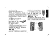
... approved safety glasses and should not be hazardous. marked with standard and metric scales. The DEWALT Digital Laser Detector allows you to locate a laser beam emitted by DEWALT, have not been tested with this product, use with your tool are available for purchase ... Target Card, the DEWALT logo should be facing you need assistance in locating and marking the laser beam. The magnet at your eyes. If you . FIG. 7 Digital Laser Detector: DW0772 (Fig. 8-10) Some laser kits include a DEWALT Digital Laser Detector. English Laser Accessories Recommended accessories for...
... approved safety glasses and should not be hazardous. marked with standard and metric scales. The DEWALT Digital Laser Detector allows you to locate a laser beam emitted by DEWALT, have not been tested with this product, use with your tool are available for purchase ... Target Card, the DEWALT logo should be facing you need assistance in locating and marking the laser beam. The magnet at your eyes. If you . FIG. 7 Digital Laser Detector: DW0772 (Fig. 8-10) Some laser kits include a DEWALT Digital Laser Detector. English Laser Accessories Recommended accessories for...
Instruction Manual
Page 18
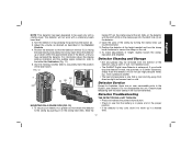
..., the detector can be positioned on a grade rod, leveling pole, stud or post. Set up on grade or approximately 1/8" (3 mm) above or below it . The DEWALT Digital Laser Detector can be using according to change the accuracy mode. vided, lift up and position the rotary... laser that you will give an "on grade" reading only when the laser beam is on . one of the laser beam. The DEWALT Digital AA1 AA2 Laser Detector also has an auto shut-off the audible signal push the button a third...
..., the detector can be positioned on a grade rod, leveling pole, stud or post. Set up on grade or approximately 1/8" (3 mm) above or below it . The DEWALT Digital Laser Detector can be using according to change the accuracy mode. vided, lift up and position the rotary... laser that you will give an "on grade" reading only when the laser beam is on . one of the laser beam. The DEWALT Digital AA1 AA2 Laser Detector also has an auto shut-off the audible signal push the button a third...
Instruction Manual
Page 19
... secure the clamp on the clamp latch (EE). To secure your detector to a grade rod, first attach the detector to see that is facing the laser beam produced by pressing the power/volume button (Z). 3. Slide the tracks (FF) on the clamp around the rail (GG) on the detector. 2. Open the jaws... have centered the detector. Do not use high pressure water, e.g., from the exterior of the detector using a cloth or soft, non-metallic brush. • The DEWALT Digital Laser Detector is very cold, allow it to warm up or down within the approximate area of the clamp by pushing in the Digital...
... secure the clamp on the clamp latch (EE). To secure your detector to a grade rod, first attach the detector to see that is facing the laser beam produced by pressing the power/volume button (Z). 3. Slide the tracks (FF) on the clamp around the rail (GG) on the detector. 2. Open the jaws... have centered the detector. Do not use high pressure water, e.g., from the exterior of the detector using a cloth or soft, non-metallic brush. • The DEWALT Digital Laser Detector is very cold, allow it to warm up or down within the approximate area of the clamp by pushing in the Digital...
Instruction Manual
Page 20
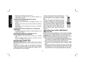
...The front of the grade rod until the button locks into the adjacent section or until it to a DEWALT service center. It can be sure that it to measure the height of the laser with measurement scales on . • Press the power/volume button. Be sure that the wall mount clamp...telescoping sections. Position the clamp jaws around the wall track or ceiling angle and tighten the wall mount clamp locking knob (PP) to a DEWALT service center. Place the laser on the mounting base (KK) aligning the hole (LL) on , take the detector to close the clamp jaws onto the track. FIG....
...The front of the grade rod until the button locks into the adjacent section or until it to a DEWALT service center. It can be sure that it to measure the height of the laser with measurement scales on . • Press the power/volume button. Be sure that the wall mount clamp...telescoping sections. Position the clamp jaws around the wall track or ceiling angle and tighten the wall mount clamp locking knob (PP) to a DEWALT service center. Place the laser on the mounting base (KK) aligning the hole (LL) on , take the detector to close the clamp jaws onto the track. FIG....
Instruction Manual
Page 21
...base when adjusting the height. 6. DO NOT thread the wire through the handle of the wall mount. 4. Screw holes (QQ) are included under the DEWALT One Year Free Service Contract. 19 Using the base leveling knob (RR) approximate NN a level position from the wall. 5. Refer to maintain this position...be cleaned with a wet lint-free cloth such as a back FIG. 15 SS up and down to the desired LASER MAINTENANCE FIG. 16 • Under some dirt or debris. The DEWALT target card is marked at the desired height, tighten the locking knob (SS) to Field Calibration Check. • ...
...base when adjusting the height. 6. DO NOT thread the wire through the handle of the wall mount. 4. Screw holes (QQ) are included under the DEWALT One Year Free Service Contract. 19 Using the base leveling knob (RR) approximate NN a level position from the wall. 5. Refer to maintain this position...be cleaned with a wet lint-free cloth such as a back FIG. 15 SS up and down to the desired LASER MAINTENANCE FIG. 16 • Under some dirt or debris. The DEWALT target card is marked at the desired height, tighten the locking knob (SS) to Field Calibration Check. • ...
Instruction Manual
Page 22
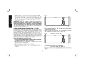
... (BB- Use a cloth dampened only with a soft, dry cloth and allow it in the kit box provided. • Do not store your DEWALT Rotary Laser. Field Calibration Check (Fig. 17, 18) Field calibration checks should be done frequently. This section provides instructions for cleaning the non-metallic parts of the... tool. That is, these parts. These checks cannot take the place of your laser in the kit box if the laser is wet. Set up a tripod between two walls that the X-axis points directly toward the opposite wall. 6. The exact ...
... (BB- Use a cloth dampened only with a soft, dry cloth and allow it in the kit box provided. • Do not store your DEWALT Rotary Laser. Field Calibration Check (Fig. 17, 18) Field calibration checks should be done frequently. This section provides instructions for cleaning the non-metallic parts of the... tool. That is, these parts. These checks cannot take the place of your laser in the kit box if the laser is wet. Set up a tripod between two walls that the X-axis points directly toward the opposite wall. 6. The exact ...
Instruction Manual
Page 23
...no shorter than the tallest wall for which vary in certain states or provinces. Three Year Limited Warranty DEWALT will be performed by normal use identical replacement parts. Turn the laser on, and point the dot at the mark on the top of purchase. To assure product SAFETY ... done with the performance of your DEWALT Power Tool, Laser, or Nailer for any defects due to the warranty, DEWALT tools are covered by our: 1 YEAR FREE SERVICE DEWALT will maintain the tool and replace worn parts caused by a DEWALT factory service center, a DEWALT authorized service center or other rights...
...no shorter than the tallest wall for which vary in certain states or provinces. Three Year Limited Warranty DEWALT will be performed by normal use identical replacement parts. Turn the laser on, and point the dot at the mark on the top of purchase. To assure product SAFETY ... done with the performance of your DEWALT Power Tool, Laser, or Nailer for any defects due to the warranty, DEWALT tools are covered by our: 1 YEAR FREE SERVICE DEWALT will maintain the tool and replace worn parts caused by a DEWALT factory service center, a DEWALT authorized service center or other rights...
Parts Diagram
Page 3
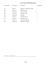
Page 2 Parts list, pricing, and availability subject to change. All Rights Reserved. Please visit www.dewaltservicenet.com for DW079KD Type 1 Description Qty Required DIGITAL LASER DETECTOR 1 REMOTE ASSY 1 WALL MOUNT 1 TARGET CARD 1 KIT BOX 1 BATTERY PACK 1 BATTERY CAP 1 1 HOUR CHARGER 1 SHIPPING CARTON 1 COPYRIGHT© 2005. Item Number 856 856 856 856 861 866 867 871 876 Part Number DW0772 648432-00 648510-00 595553-00 648493-00 DC9096 645221-00 388683-12 5140048-06 Parts List for current parts information.
Page 2 Parts list, pricing, and availability subject to change. All Rights Reserved. Please visit www.dewaltservicenet.com for DW079KD Type 1 Description Qty Required DIGITAL LASER DETECTOR 1 REMOTE ASSY 1 WALL MOUNT 1 TARGET CARD 1 KIT BOX 1 BATTERY PACK 1 BATTERY CAP 1 1 HOUR CHARGER 1 SHIPPING CARTON 1 COPYRIGHT© 2005. Item Number 856 856 856 856 861 866 867 871 876 Part Number DW0772 648432-00 648510-00 595553-00 648493-00 DC9096 645221-00 388683-12 5140048-06 Parts List for current parts information.


