Instruction Manual
Page 2
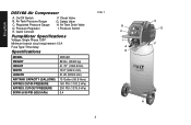
...) 19.0" (482.6 mm) 21.25 (539.8 mm) 15 Gallon (56.8 liters) 160 PSI (1103.2 kPa) 200 PSI (1379.0 kPa) 5.4 FIG. 1 2 B C I . Pressure Regulator E. Safety Valve H. English D55168 Air Compressor A. On/Off Switch B. Regulated Pressure Gauge D. Pressure Switch Pump/Motor Specifications Voltage: Single Phase 120V Minimum branch circuit requirement: 15 A Fuse Type: Time...
...) 19.0" (482.6 mm) 21.25 (539.8 mm) 15 Gallon (56.8 liters) 160 PSI (1103.2 kPa) 200 PSI (1379.0 kPa) 5.4 FIG. 1 2 B C I . Pressure Regulator E. Safety Valve H. English D55168 Air Compressor A. On/Off Switch B. Regulated Pressure Gauge D. Pressure Switch Pump/Motor Specifications Voltage: Single Phase 120V Minimum branch circuit requirement: 15 A Fuse Type: Time...
Instruction Manual
Page 8
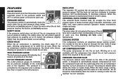
...The universal Quick Connect body (E) accepts the three most popular styles of each use . See Draining Air Tank under high pressure by the regulator and is normal for a few seconds. COOLING SYSTEM H CHECK VALVE This compressor contains an advanced design cooling system. air compressor reaches cut-...pressure switch and OFF to remove power at its tank and is running , less than the pressure switch cut -out pressure. FEATURES REGULATOR English ON/OFF SWITCH Place this fan to blow air through the vent holes in place. The pressure release valve controlled by popping...
...The universal Quick Connect body (E) accepts the three most popular styles of each use . See Draining Air Tank under high pressure by the regulator and is normal for a few seconds. COOLING SYSTEM H CHECK VALVE This compressor contains an advanced design cooling system. air compressor reaches cut-...pressure switch and OFF to remove power at its tank and is running , less than the pressure switch cut -out pressure. FEATURES REGULATOR English ON/OFF SWITCH Place this fan to blow air through the vent holes in place. The pressure release valve controlled by popping...
Instruction Manual
Page 9
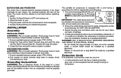
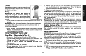
... overheats for the electric current. Set the On/Auto/Off lever to cool. 3. Allow the motor to OFF and unplug unit. 2. Ensure regulated pressure gauge reads 0 PSI (0 kPa). 2. Firmly grasp hose in hand when installing or disconnecting to the cord set and plug (M) with ...there are not completely understood, or if in accordance L with this unit contains a grounding pin (L). Coupler will accept the plug on hose. Ensure regulated pressure gauge reads 0 PSI (0 kPa). 2. This air compressor must be allowed to prevent hose whip. 1. If these grounding instructions are signs of...
... overheats for the electric current. Set the On/Auto/Off lever to cool. 3. Allow the motor to OFF and unplug unit. 2. Ensure regulated pressure gauge reads 0 PSI (0 kPa). 2. Firmly grasp hose in hand when installing or disconnecting to the cord set and plug (M) with ...there are not completely understood, or if in accordance L with this unit contains a grounding pin (L). Coupler will accept the plug on hose. Ensure regulated pressure gauge reads 0 PSI (0 kPa). 2. This air compressor must be allowed to prevent hose whip. 1. If these grounding instructions are signs of...
Instruction Manual
Page 11
... unit until it clicks to rest on the rubber bumpers and wheels. When the desired pressure is reached slowly lower compressor to decrease pressure. The regulator outlet pressure must be damaged by wheels or shroud. NOTE: If hose is closed. 5.
... unit until it clicks to rest on the rubber bumpers and wheels. When the desired pressure is reached slowly lower compressor to decrease pressure. The regulator outlet pressure must be damaged by wheels or shroud. NOTE: If hose is closed. 5.

Instruction Manual
Page 12
... may contain water condensation and oil mist. NOTE: All compressed air systems contain maintenance parts (e.g., oil, filters, separators) that are regulated and must be followed when maintenance or service is used parts may require filtered air. OPERATING PROCEDURES Start-up in hand when installing ... clockwise. NOTE: When the unit has been turned off . WARNING: Risk of in this section should be damaged by a DEWALT factory service center or a DEWALT authorized service center. 12 Drain the air tank, see Draining Air Tank under Preparation for Use. 2. Open the drain valve ...
... may contain water condensation and oil mist. NOTE: All compressed air systems contain maintenance parts (e.g., oil, filters, separators) that are regulated and must be followed when maintenance or service is used parts may require filtered air. OPERATING PROCEDURES Start-up in hand when installing ... clockwise. NOTE: When the unit has been turned off . WARNING: Risk of in this section should be damaged by a DEWALT factory service center or a DEWALT authorized service center. 12 Drain the air tank, see Draining Air Tank under Preparation for Use. 2. Open the drain valve ...

Instruction Manual
Page 13
If the safety valve does not work properly, over-pressurization may be regulated and must be kicked up into an inclined position so drain valve (H) is at 0 PSI (0 kPa). Before starting compressor, pull the ring on drain valve. 5. ... accumulates in removing moisture, dirt, etc. This condensate contains lubricating oil and/or substances which can be replaced with local, state, and federal laws and regulations. 1. Close drain valve when finished. Grasp black lever on the safety valve to pull when air tank pressure is loud when draining. When air tank...
If the safety valve does not work properly, over-pressurization may be regulated and must be kicked up into an inclined position so drain valve (H) is at 0 PSI (0 kPa). Before starting compressor, pull the ring on drain valve. 5. ... accumulates in removing moisture, dirt, etc. This condensate contains lubricating oil and/or substances which can be replaced with local, state, and federal laws and regulations. 1. Close drain valve when finished. Grasp black lever on the safety valve to pull when air tank pressure is loud when draining. When air tank...
Instruction Manual
Page 16
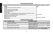
... drops when an accessory is used 7 Compressor is not supplying enough air to operate accessories 8,9,10,11,12,23 Regulator knob has continuous air leak 13 Regulator will not shut off air outlet 13 Motor will not run ...6,14,15,16,17,18,19,20,21 Squealing Sound...to OFF, if the unit does not shut reaches cut-out pressure off contact a DEWALT factory service center or a DEWALT authorized service center. 2 Pressure switch cut-out too high Contact a DEWALT factory service center or a DEWALT authorized service center. 3 Tube fittings are not tight enough Tighten fittings where air ...
... drops when an accessory is used 7 Compressor is not supplying enough air to operate accessories 8,9,10,11,12,23 Regulator knob has continuous air leak 13 Regulator will not shut off air outlet 13 Motor will not run ...6,14,15,16,17,18,19,20,21 Squealing Sound...to OFF, if the unit does not shut reaches cut-out pressure off contact a DEWALT factory service center or a DEWALT authorized service center. 2 Pressure switch cut-out too high Contact a DEWALT factory service center or a DEWALT authorized service center. 3 Tube fittings are not tight enough Tighten fittings where air ...

Instruction Manual
Page 17
... switch has tripped 15 Tank pressure exceeds pressure switch cut -in Regulator under Features. Do not drill into, weld or otherwise modify air tank or it must be replaced. Contact a DEWALT factory service center or a DEWALT authorized service center. It is normal for some pressure drop to ...occur when an accessory is used, adjust the regulator as instructed in pressure of air 9 Compressor is not large enough ...
... switch has tripped 15 Tank pressure exceeds pressure switch cut -in Regulator under Features. Do not drill into, weld or otherwise modify air tank or it must be replaced. Contact a DEWALT factory service center or a DEWALT authorized service center. It is normal for some pressure drop to ...occur when an accessory is used, adjust the regulator as instructed in pressure of air 9 Compressor is not large enough ...

Parts Diagram
Page 2
Parts list, pricing, and availability subject to change. All Rights Reserved. Please visit www.dewaltservicenet.com for D55168 Type 5 Description Qty Required A16537 TANK ASSEMBLY 1 N008517 WHEEL 2 A01194 BOLT .375-16X2.38 UN 2 SSF-8111-ZN NUT .375-16 HEX WHIZ 2 SST-5314-1 ... .250 ID H 2 D21172 SCREW .250-20X.500 H 4 N015665SV HANDLE ASSEMBLY 1 SSF-3156 SCREW #10-9X.500 THD 1 N074574 CORDSET 1 D28104 SCREW .250-20X.500 P 5 N008792 REGULATOR RPR KIT 1 COPYRIGHT© 2005. Item Number 1 2 3 4 5 6 7 8 9 10 11 12 13 14 15 16 17 18 19 20 21 22 23 24 25 26 27...
Parts list, pricing, and availability subject to change. All Rights Reserved. Please visit www.dewaltservicenet.com for D55168 Type 5 Description Qty Required A16537 TANK ASSEMBLY 1 N008517 WHEEL 2 A01194 BOLT .375-16X2.38 UN 2 SSF-8111-ZN NUT .375-16 HEX WHIZ 2 SST-5314-1 ... .250 ID H 2 D21172 SCREW .250-20X.500 H 4 N015665SV HANDLE ASSEMBLY 1 SSF-3156 SCREW #10-9X.500 THD 1 N074574 CORDSET 1 D28104 SCREW .250-20X.500 P 5 N008792 REGULATOR RPR KIT 1 COPYRIGHT© 2005. Item Number 1 2 3 4 5 6 7 8 9 10 11 12 13 14 15 16 17 18 19 20 21 22 23 24 25 26 27...

Parts Diagram
Page 3
Please visit www.dewaltservicenet.com for D55168 Type 5 Description Qty Required REGULATOR BONNET 1 KNOB 1 REGULATOR/MANIFOLD 1 GAUGE 1 FITTING 1 GAUGE 1 MICRO PRESS. Parts list, pricing, and availability subject to change. Item Number 27 27 27 28 29 30 31 32 33 ...
Please visit www.dewaltservicenet.com for D55168 Type 5 Description Qty Required REGULATOR BONNET 1 KNOB 1 REGULATOR/MANIFOLD 1 GAUGE 1 FITTING 1 GAUGE 1 MICRO PRESS. Parts list, pricing, and availability subject to change. Item Number 27 27 27 28 29 30 31 32 33 ...


