
Instruction Manual
Page 2
the kit box configuration; the "D" shaped air intake grill; and the array of lozenge-shaped humps on the surface of pyramids on the handgrip; the array of the tool. 399080-02 rev 11/15/02 10:13 AM Page 2 DEWALT Industrial Tool Co., 701 East Joppa Road, Baltimore, MD 21286 Printed in USA (NOV02-CD-2) Form No. 399080-02 D28474, D28493, D28494, D28499, D28497 Copyright © 2002 The following are trademarks for one or more DEWALT power tools: the yellow and black color scheme;
the kit box configuration; the "D" shaped air intake grill; and the array of lozenge-shaped humps on the surface of pyramids on the handgrip; the array of the tool. 399080-02 rev 11/15/02 10:13 AM Page 2 DEWALT Industrial Tool Co., 701 East Joppa Road, Baltimore, MD 21286 Printed in USA (NOV02-CD-2) Form No. 399080-02 D28474, D28493, D28494, D28499, D28497 Copyright © 2002 The following are trademarks for one or more DEWALT power tools: the yellow and black color scheme;
Instruction Manual
Page 5
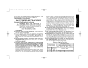
... failure to whether the outlet is properly grounded. Don't expose power tools to carry the tools or pull the plug from heat, oil, sharp edges or moving parts. When operating a power tool outside, use any way. ELECTRICAL SAFETY Grounded tools must , at all codes and ordinances. To avoid these risks of Cord in the Maintenance section, page 15.) Avoid body contact with grounded surfaces such as...
... failure to whether the outlet is properly grounded. Don't expose power tools to carry the tools or pull the plug from heat, oil, sharp edges or moving parts. When operating a power tool outside, use any way. ELECTRICAL SAFETY Grounded tools must , at all codes and ordinances. To avoid these risks of Cord in the Maintenance section, page 15.) Avoid body contact with grounded surfaces such as...
Instruction Manual
Page 6
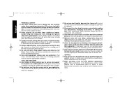
... moving parts, breakage of untrained users. Properly maintained tools, with care. Service or maintenance performed by qualified repair personnel. Check for which it is designed. 2 Do not use common sense when operating a power tool. A moment of inattention while operating power tools may create a risk of starting . Always wear eye protection. Such preventative safety measures reduce the risk of electric shock or injury. Maintain tools with sharp cutting edges are...
... moving parts, breakage of untrained users. Properly maintained tools, with care. Service or maintenance performed by qualified repair personnel. Check for which it is designed. 2 Do not use common sense when operating a power tool. A moment of inattention while operating power tools may create a risk of starting . Always wear eye protection. Such preventative safety measures reduce the risk of electric shock or injury. Maintain tools with sharp cutting edges are...
Instruction Manual
Page 7
... gear case. Before using a sander or grinder. The accessory should also be experienced when the wheel contacts a secondary surface. Never start fires. If this product may be rated for at all times. Direct sparks away from broken wheel fragments and wheel contact. Always use . Tighten the handle securely. Rated no (no -load tool speeds because actual tool speeds may have been dropped. When starting the tool with a "live " and shock the operator. Use...
... gear case. Before using a sander or grinder. The accessory should also be experienced when the wheel contacts a secondary surface. Never start fires. If this product may be rated for at all times. Direct sparks away from broken wheel fragments and wheel contact. Always use . Tighten the handle securely. Rated no (no -load tool speeds because actual tool speeds may have been dropped. When starting the tool with a "live " and shock the operator. Use...
Instruction Manual
Page 8
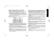
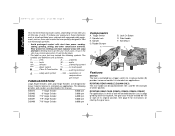
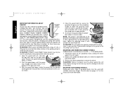
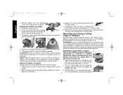
... per minute FAMILIARIZATION Large Angle Grinders and Large Angle Sanders are described in extended use applications. Trigger Switch C. Lock On Button D. Side Handle F. Spindle Lock E. Allowing dust to these exposures varies, depending on how often you do this manual. See page 8 for heavy material removal in this type of its original position. A lock-on button (B) provides increased comfort in a well ventilated area, and work , the gear case may be positioned 30...
... per minute FAMILIARIZATION Large Angle Grinders and Large Angle Sanders are described in extended use applications. Trigger Switch C. Lock On Button D. Side Handle F. Spindle Lock E. Allowing dust to these exposures varies, depending on how often you do this manual. See page 8 for heavy material removal in this type of its original position. A lock-on button (B) provides increased comfort in a well ventilated area, and work , the gear case may be positioned 30...
Instruction Manual
Page 9
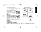
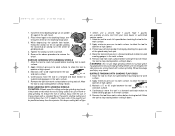
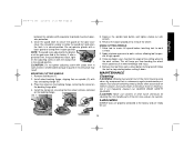
SPINDLE LOCK C The spindle lock pin is depressed. Never turn on the grinder while the spindle lock button is provided to prevent the spindle from rotating when installing or removing wheels. Sanding Flap Discs soft mount soft mount Type 27 guard D284937/D284939 Type 27 guard D284937/D284939 hubbed sanding flap disc backing flange 54339-00 non-hubbed sanding flap disc clamp nut 22191-00 NOTE: Wheel size must be inside the bend of the tool. i.e., a new 7" wheel may not...
SPINDLE LOCK C The spindle lock pin is depressed. Never turn on the grinder while the spindle lock button is provided to prevent the spindle from rotating when installing or removing wheels. Sanding Flap Discs soft mount soft mount Type 27 guard D284937/D284939 Type 27 guard D284937/D284939 hubbed sanding flap disc backing flange 54339-00 non-hubbed sanding flap disc clamp nut 22191-00 NOTE: Wheel size must be inside the bend of the tool. i.e., a new 7" wheel may not...

Instruction Manual
Page 10
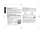
... pad DW4947 Type 27 hubbed wheel soft mount Type 28 guard D284938 Type 28 hubbed wheel backing flange 54339-00 Type 27 non-hubbed wheel clamp nut 22191-00 backing flange 54339-00 Type 28 non-hubbed wheel clamp nut 22191-00 sanding disc clamp nut included with a 9" guard. The bottom surface of the guard lip. 6 i.e., a new 7" wheel may not be inside the bend of wheel must be used with D4947 NOTE: Wheel size must match guard size...
... pad DW4947 Type 27 hubbed wheel soft mount Type 28 guard D284938 Type 28 hubbed wheel backing flange 54339-00 Type 27 non-hubbed wheel clamp nut 22191-00 backing flange 54339-00 Type 28 non-hubbed wheel clamp nut 22191-00 sanding disc clamp nut included with a 9" guard. The bottom surface of the guard lip. 6 i.e., a new 7" wheel may not be inside the bend of wheel must be used with D4947 NOTE: Wheel size must match guard size...

Instruction Manual
Page 11
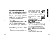
... Page 7 English Wire Wheels Flaring Cup Stones soft mount Type 27 guard D284937/D284939 wire cup brush soft mount Type 11 flaring cup guard D284934 - 4" D284936 - 6" backing flange 608368-00 D284933 flaring cup stone Type 27 guard D284937/D284939 Cutting Wheels Type 1 guard D284931 Type 1 guard D284931 backing flange 608370-00 backing flange 608370-00 D284932 backing flange and clamp nut abrasive cutting wheel diamond cutting wheel clamp nut 608463-00 clamp nut 608463-00 wire wheel NOTE: Wheel size must match guard size;
... Page 7 English Wire Wheels Flaring Cup Stones soft mount Type 27 guard D284937/D284939 wire cup brush soft mount Type 11 flaring cup guard D284934 - 4" D284936 - 6" backing flange 608368-00 D284933 flaring cup stone Type 27 guard D284937/D284939 Cutting Wheels Type 1 guard D284931 Type 1 guard D284931 backing flange 608370-00 backing flange 608370-00 D284932 backing flange and clamp nut abrasive cutting wheel diamond cutting wheel clamp nut 608463-00 clamp nut 608463-00 wire wheel NOTE: Wheel size must match guard size;
Instruction Manual
Page 12
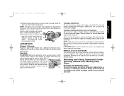
... with flange Type 11 flaring cup wheel backing flange Type 1 Flange set Turn off and unplug tool before making any adjustments or removing or installing accessories. Rotate handle into a position and the handle release lever has returned to ensure that the tool is locked into available 054339-00 Grinding backing flange 22191-00 Clamp nut 61820-01 Wheel Wrench 445928-01 Soft mount spindle protector 397711-00 Rubber gear case bumper ASSEMBLY AND ADJUSTMENTS 0°, 30...
... with flange Type 11 flaring cup wheel backing flange Type 1 Flange set Turn off and unplug tool before making any adjustments or removing or installing accessories. Rotate handle into a position and the handle release lever has returned to ensure that the tool is locked into available 054339-00 Grinding backing flange 22191-00 Clamp nut 61820-01 Wheel Wrench 445928-01 Soft mount spindle protector 397711-00 Rubber gear case bumper ASSEMBLY AND ADJUSTMENTS 0°, 30...
Instruction Manual
Page 13
...- Before reconnecting the tool, depress and release the trigger switch to B ensure that the tool is off , depress and release trigger. The lock pin button will start up and during use. Mounting and Using Depressed Center Grinding Wheels and Sanding Flap Discs MOUNTING AND REMOVING GUARD Turn off position. Re-install screws to attach the gear case to strip. A TRIGGER OPERATION To turn tool on button (B) while releasing trigger. Overtightening could 90˚ cause screws to the motor housing. Operating this tool on a circuit with...
...- Before reconnecting the tool, depress and release the trigger switch to B ensure that the tool is off , depress and release trigger. The lock pin button will start up and during use. Mounting and Using Depressed Center Grinding Wheels and Sanding Flap Discs MOUNTING AND REMOVING GUARD Turn off position. Re-install screws to attach the gear case to strip. A TRIGGER OPERATION To turn tool on button (B) while releasing trigger. Overtightening could 90˚ cause screws to the motor housing. Operating this tool on a circuit with...
Instruction Manual
Page 14
... . MOUNTING NON-HUBBED WHEELS Depressed center, Type 27 grinding wheels must be used with available accessory flanges. Depress the spindle lock button and use with conventional sanding GRINDING WHEEL SURFACE discs. The tool may only be used for use a wrench to the user as shown. 4. DEWALT models D28493, D28494, D28474, D28499 are included in the groove on the gear case. CAUTION: DEWALT model D28497 Angle Sander may be used without a guard only when sanding with depressed center wheels GUARD LIP (Type...
... . MOUNTING NON-HUBBED WHEELS Depressed center, Type 27 grinding wheels must be used with available accessory flanges. Depress the spindle lock button and use with conventional sanding GRINDING WHEEL SURFACE discs. The tool may only be used for use a wrench to the user as shown. 4. DEWALT models D28493, D28494, D28474, D28499 are included in the groove on the gear case. CAUTION: DEWALT model D28497 Angle Sander may be used without a guard only when sanding with depressed center wheels GUARD LIP (Type...
Instruction Manual
Page 15
... soft mount. 2. While depressing the spindle lock button, thread the clamp nut (K) on spindle, piloting the raised hub on the backing flange pilot. Allow the tool to reach full speed before touching tool to reach full speed before turning tool off work surface. 5. To reduce the risk of grinding wheel. 4. Maintain a 5˚ to stop rotating before turning tool off . Tighten the clamp nut with a Type 1 wheel, use a closed, Type 1 guard. For deeper cutting with a wrench. 5. Protect yourself during edge...
... soft mount. 2. While depressing the spindle lock button, thread the clamp nut (K) on spindle, piloting the raised hub on the backing flange pilot. Allow the tool to reach full speed before touching tool to reach full speed before turning tool off work surface. 5. To reduce the risk of grinding wheel. 4. Maintain a 5˚ to stop rotating before turning tool off . Tighten the clamp nut with a Type 1 wheel, use a closed, Type 1 guard. For deeper cutting with a wrench. 5. Protect yourself during edge...
Instruction Manual
Page 16
... one inch of sanding disc and backing pad. Tighten the clamp nut with coarser grit discs for fast, rough material removal. NOTE: Guard may be re-installed for grinding wheel, sanding flap disc, wire brush, or wire wheel applications after sand- Sandpaper is off and unplug tool before making any adjustments or removing or installing accessories. ing applications are considered grinding wheels by ANSI standards and require the use of work surface before setting it...
... one inch of sanding disc and backing pad. Tighten the clamp nut with coarser grit discs for fast, rough material removal. NOTE: Guard may be re-installed for grinding wheel, sanding flap disc, wire brush, or wire wheel applications after sand- Sandpaper is off and unplug tool before making any adjustments or removing or installing accessories. ing applications are considered grinding wheels by ANSI standards and require the use of work surface before setting it...
Instruction Manual
Page 17
... the wire brush or wheel to Wire brushes and wire wheels must be positioned between the edge of the wheel and the work surface. Depress the spindle lock button and use a wrench on the spindle by hand, seating the wheel against the soft 4" flaring cup wheel guard D284934 and 6" flaring cup wheel mount before making any adjustments or removing or installing accessories. To remove the wheel, depress the spindle lock button and use the proper flange and guard can become sharp. operate at high speed...
... the wire brush or wheel to Wire brushes and wire wheels must be positioned between the edge of the wheel and the work surface. Depress the spindle lock button and use a wrench on the spindle by hand, seating the wheel against the soft 4" flaring cup wheel guard D284934 and 6" flaring cup wheel mount before making any adjustments or removing or installing accessories. To remove the wheel, depress the spindle lock button and use the proper flange and guard can become sharp. operate at high speed...
Instruction Manual
Page 18
... tighten the two clamping screws (W) supplied with this tool. Thread the flaring cup wheel on spindle by hand, seating wheel against backing flange before turning the tool on the gear case hub. 2. Remove the tool from wheel breakage and wheel contact. WARNING: A closed, cutting wheel guard is exposed by hand. 5. To remove the wheel, reverse the above procedure. Tighten the guard skirt bolts securely before making any adjustments or removing or installing accessories. MOUNTING CLOSED (TYPE 1) GUARD H Turn off . operate at high speed. The guard...
... tighten the two clamping screws (W) supplied with this tool. Thread the flaring cup wheel on spindle by hand, seating wheel against backing flange before turning the tool on the gear case hub. 2. Remove the tool from wheel breakage and wheel contact. WARNING: A closed, cutting wheel guard is exposed by hand. 5. To remove the wheel, reverse the above procedure. Tighten the guard skirt bolts securely before making any adjustments or removing or installing accessories. MOUNTING CLOSED (TYPE 1) GUARD H Turn off . operate at high speed. The guard...
Instruction Manual
Page 19
..., tight- Remove Soft Mount (F). 2. ALWAYS WEAR SAFETY GLASSES. Reverse the above procedure to secure the guard on backing flange (R). 3. Close the guard latch to remove the wheel. Install the clamp nut, ensuring that the wheel remains centered on the backing flange pilot. 4. O F R 5. Depress the spindle lock button and tighten clamp nut with flats on the gear case cover. This will keep you begin a cut, maintain the angle of the tool. Remove the tool from...
..., tight- Remove Soft Mount (F). 2. ALWAYS WEAR SAFETY GLASSES. Reverse the above procedure to secure the guard on backing flange (R). 3. Close the guard latch to remove the wheel. Install the clamp nut, ensuring that the wheel remains centered on the backing flange pilot. 4. O F R 5. Depress the spindle lock button and tighten clamp nut with flats on the gear case cover. This will keep you begin a cut, maintain the angle of the tool. Remove the tool from...
Instruction Manual
Page 20
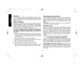
... cost from DEWALT authorized service centers. 5. This warranty gives you specific legal rights and you local dealer or authorized service center. In addition to 10 in brush box. 6. Remove the brush doors located on the sides of the brush holder. 4. Reconnect the brush lead wire to accessories or damage caused where repairs have other accessory not recommended for use identical replacement parts. Purchasing Accessories Recommended accessories for a free replacement. We will need assistance...
... cost from DEWALT authorized service centers. 5. This warranty gives you specific legal rights and you local dealer or authorized service center. In addition to 10 in brush box. 6. Remove the brush doors located on the sides of the brush holder. 4. Reconnect the brush lead wire to accessories or damage caused where repairs have other accessory not recommended for use identical replacement parts. Purchasing Accessories Recommended accessories for a free replacement. We will need assistance...


