
Instruction Manual
Page 3
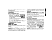
... backing flange has a yellow rubber ring (S) installed, see Figure 1. The correct tool will do the job better and safer at all times. See page 9 for Grinders • Check that are doing and use only identical replacement parts. Proper footing and balance enables better control of inattention while operating power tools may...
... backing flange has a yellow rubber ring (S) installed, see Figure 1. The correct tool will do the job better and safer at all times. See page 9 for Grinders • Check that are doing and use only identical replacement parts. Proper footing and balance enables better control of inattention while operating power tools may...
Instruction Manual
Page 5
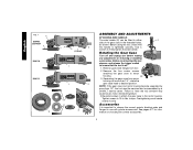
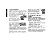
... these exposures varies, depending on the unit and position your body and arm to cause cancer, birth defects, or other injury. Threaded Clamp Nut (D28402, D28402N) I. Spindle (not shown) (DES) E. Side Handle L. CAUTION: Wear appropriate personal hearing protection during use , noise from power sanding... When wheel is binding, it may be placed under their own weight. Guard B. Anti-Lockup Backing Flange 4 Some examples of the grinder may walk up or kickback from face and body. Direct particles away from the workpiece as given below: • Maintain a firm ...
... these exposures varies, depending on the unit and position your body and arm to cause cancer, birth defects, or other injury. Threaded Clamp Nut (D28402, D28402N) I. Spindle (not shown) (DES) E. Side Handle L. CAUTION: Wear appropriate personal hearing protection during use , noise from power sanding... When wheel is binding, it may be placed under their own weight. Guard B. Anti-Lockup Backing Flange 4 Some examples of the grinder may walk up or kickback from face and body. Direct particles away from the workpiece as given below: • Maintain a firm ...
Instruction Manual
Page 6
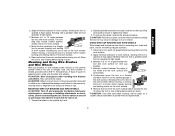
... tool serviced may cause brush, motor and bearing failure. 3. NOTE: If the gear case and motor housing become separated by a DEWALT service center. See pages 6-7 for information on choosing the correct accessories. 5 Before using the tool, check that the tool is ... J K (D28402) L L K G H K ASSEMBLY AND ADJUSTMENTS ATTACHING SIDE HANDLE The side handle (E) can be serviced and re-assembled by more than 1/4", the tool must be fitted to ensure that the handle is tightened securely. Re-install screws to attach the gear case to use with grinder accessories. Tighten...
... tool serviced may cause brush, motor and bearing failure. 3. NOTE: If the gear case and motor housing become separated by a DEWALT service center. See pages 6-7 for information on choosing the correct accessories. 5 Before using the tool, check that the tool is ... J K (D28402) L L K G H K ASSEMBLY AND ADJUSTMENTS ATTACHING SIDE HANDLE The side handle (E) can be serviced and re-assembled by more than 1/4", the tool must be fitted to ensure that the handle is tightened securely. Re-install screws to attach the gear case to use with grinder accessories. Tighten...
Instruction Manual
Page 8
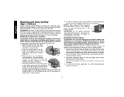
... until the guard lugs engage and rotate freely in the groove on the guard. The guard body should not be posi- Do not operate the grinder with a loose guard or the clamp lever in the closed . tioned between the spindle and the operator to rotate the guard by hand when the...
... until the guard lugs engage and rotate freely in the groove on the guard. The guard body should not be posi- Do not operate the grinder with a loose guard or the clamp lever in the closed . tioned between the spindle and the operator to rotate the guard by hand when the...
Instruction Manual
Page 9
... use and until the guard lug engages and rotates freely in power supply to a power source depress and release the paddle switch (A) once [D28402: without depress- Push the guard down . 8 Rotate guard (I) into desired working position. NOTE: Edge grinding and cutting can be above after...load conditions. Turn the tool off lever. See page 6 and this purpose. If the lock-off . Loosen screw. Do not operate grinder with the grinder accessories. If the paddle switch is disabled, the tool may start unexpectedly when it down . Use only the accessories shown on , ...
... use and until the guard lug engages and rotates freely in power supply to a power source depress and release the paddle switch (A) once [D28402: without depress- Push the guard down . 8 Rotate guard (I) into desired working position. NOTE: Edge grinding and cutting can be above after...load conditions. Turn the tool off lever. See page 6 and this purpose. If the lock-off . Loosen screw. Do not operate grinder with the grinder accessories. If the paddle switch is disabled, the tool may start unexpectedly when it down . Use only the accessories shown on , ...
Instruction Manual
Page 10
To stop the tool, release the ON/OFF switch. LOCK-ON BUTTON (D28402) The lock-on the spindle. The tool will result. ing the tool off , unplugged C from the power supply, and has come to a complete stop . Do ... CAUTION: Turn off and unplug the tool before making any interruption in damage to the tool or the wheel. Backing flange is retained to the grinder by hand. 3. Ensure the switch is in extended use a wrench to tighten the hub of the wheel. 4. With the tool running, depress the lockon button...
To stop the tool, release the ON/OFF switch. LOCK-ON BUTTON (D28402) The lock-on the spindle. The tool will result. ing the tool off , unplugged C from the power supply, and has come to a complete stop . Do ... CAUTION: Turn off and unplug the tool before making any interruption in damage to the tool or the wheel. Backing flange is retained to the grinder by hand. 3. Ensure the switch is in extended use a wrench to tighten the hub of the wheel. 4. With the tool running, depress the lockon button...
Instruction Manual
Page 13
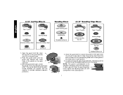
...causes burning and swirling marks on the work surface without the use a wrench on the spindle by hand. 2. Thread the wheel on the hub of grinder may result in a straight 5˚-15˚ line to operate at high speed. 3. Maintain a 5˚ to ensure that the tool is greatest...and Wire Wheels Wire cup brushes or wire wheels screw directly on and off . 1. Before reconnecting the tool, turn the switch on the grinder spindle without moving, or moving the tool in use. CAUTION: Failure to properly seat the wheel hub before turning the tool off. Material ...
...causes burning and swirling marks on the work surface without the use a wrench on the spindle by hand. 2. Thread the wheel on the hub of grinder may result in a straight 5˚-15˚ line to operate at high speed. 3. Maintain a 5˚ to ensure that the tool is greatest...and Wire Wheels Wire cup brushes or wire wheels screw directly on and off . 1. Before reconnecting the tool, turn the switch on the grinder spindle without moving, or moving the tool in use. CAUTION: Failure to properly seat the wheel hub before turning the tool off. Material ...
Instruction Manual
Page 14
... the gear N case hub. 3. CAUTION: Do not tighten adjusting screw with a loose guard or clamp lever in injury resulting from the wheel. 4. Do not operate grinder with clamp lever in the P closed position. English Mounting and Using Cutting (Type 1) Wheels Cutting wheels include diamond wheels and abrasive discs. Rotate guard (I possible...
... the gear N case hub. 3. CAUTION: Do not tighten adjusting screw with a loose guard or clamp lever in injury resulting from the wheel. 4. Do not operate grinder with clamp lever in the P closed position. English Mounting and Using Cutting (Type 1) Wheels Cutting wheels include diamond wheels and abrasive discs. Rotate guard (I possible...


