
Instruction Manual
Page 2
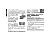
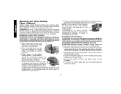
... of electric shock. • When operating a power tool outside, use any adaptor plugs. Double insulation eliminates the need for Cord Sets Volts Total Length of Cord in any way. When using an extension cord, be plugged into an outlet properly installed and grounded in accordance with a qualified electrician if you to install a polarized outlet. Failure to carry electricity away from heat, oil, sharp edges or moving parts. Cluttered...
... of electric shock. • When operating a power tool outside, use any adaptor plugs. Double insulation eliminates the need for Cord Sets Volts Total Length of Cord in any way. When using an extension cord, be plugged into an outlet properly installed and grounded in accordance with a qualified electrician if you to install a polarized outlet. Failure to carry electricity away from heat, oil, sharp edges or moving parts. Cluttered...
Instruction Manual
Page 3
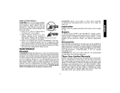
.... Service or maintenance performed by hand or against your finger on invites accidents. • Remove adjusting keys or wrenches before using. Follow instructions in the Maintenance section of the tool in tools that are easier to a stable platform. Keep your application. Proper footing and balance enables better control of this manual. Keep cutting tools sharp and clean. Additional Specific Safety Instructions for misalignment or binding of moving parts. Tools are...
.... Service or maintenance performed by hand or against your finger on invites accidents. • Remove adjusting keys or wrenches before using. Follow instructions in the Maintenance section of the tool in tools that are easier to a stable platform. Keep your application. Proper footing and balance enables better control of this manual. Keep cutting tools sharp and clean. Additional Specific Safety Instructions for misalignment or binding of moving parts. Tools are...
Instruction Manual
Page 4
... use proper guard with the wheel. Accessory ratings must be above listed minimum wheel speed as follows: V ..........volts A amperes Hz ........hertz W watts min ......minutes ....direct current ..........alternating current no............no load speed ........Class II Construction ..........safety alert symbol ........earthing terminal .../min ....revolutions per minute Causes and Operator Prevention of Kickback • Kickback is not recommended and may contain electrical wiring or piping. If grinding wheel or accessory...
... use proper guard with the wheel. Accessory ratings must be above listed minimum wheel speed as follows: V ..........volts A amperes Hz ........hertz W watts min ......minutes ....direct current ..........alternating current no............no load speed ........Class II Construction ..........safety alert symbol ........earthing terminal .../min ....revolutions per minute Causes and Operator Prevention of Kickback • Kickback is not recommended and may contain electrical wiring or piping. If grinding wheel or accessory...
Instruction Manual
Page 5
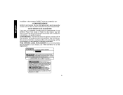
... remove the unit from this type of the grinder may occur. Always use . Paddle Switch H. Anti-Lockup Backing Flange 4 To reduce your body and arm to allow you do this product may contribute to resist kickback forces. WARNING: Use of harmful chemicals. Lock On Button (D28402) C. Spindle Lock Button K. Large panels tend to eliminate the cause of wheel pinching and kickback. Threaded Clamp Nut (D28402, D28402N) I. Dust...
... remove the unit from this type of the grinder may occur. Always use . Paddle Switch H. Anti-Lockup Backing Flange 4 To reduce your body and arm to allow you do this product may contribute to resist kickback forces. WARNING: Use of harmful chemicals. Lock On Button (D28402) C. Spindle Lock Button K. Large panels tend to eliminate the cause of wheel pinching and kickback. Threaded Clamp Nut (D28402, D28402N) I. Dust...
Instruction Manual
Page 6
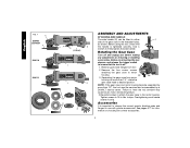
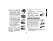
torque. Remove guard and flanges from motor housing not more than 1/4", rotate the gear case head to desired position. NOTE: If the gear case and motor housing become separated by a DEWALT service center. Re-install screws to attach the gear case to firmly tighten the side handle. Before reconnecting the tool, depress and release the trigger switch to ensure that the handle is tightened securely. Accessories It is off and unplug tool before making any adjustments or removing or...
torque. Remove guard and flanges from motor housing not more than 1/4", rotate the gear case head to desired position. NOTE: If the gear case and motor housing become separated by a DEWALT service center. Re-install screws to attach the gear case to firmly tighten the side handle. Before reconnecting the tool, depress and release the trigger switch to ensure that the handle is tightened securely. Accessories It is off and unplug tool before making any adjustments or removing or...
Instruction Manual
Page 7
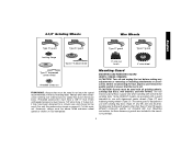
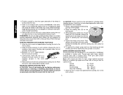
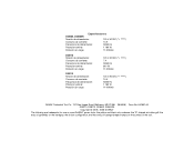
.... Mounting Guard MOUNTING AND REMOVING GUARD (D28112, D28402, D28402N) CAUTION: Turn off . CAUTION: Guards must be rated for use with sanding flap discs (Type 27 and 29) and wire brushes. Every unthreaded accessory must have a 7/8" arbor hole. Before reconnecting the tool, depress and release the paddle switch to ensure that the tool is designed for a circular saw and should not be used without a guard only when sanding with conventional sanding discs. 4-1/2" Grinding Wheels Wire Wheels English Type 27 guard Type 27 guard Type...
.... Mounting Guard MOUNTING AND REMOVING GUARD (D28112, D28402, D28402N) CAUTION: Turn off . CAUTION: Guards must be rated for use with sanding flap discs (Type 27 and 29) and wire brushes. Every unthreaded accessory must have a 7/8" arbor hole. Before reconnecting the tool, depress and release the paddle switch to ensure that the tool is designed for a circular saw and should not be used without a guard only when sanding with conventional sanding discs. 4-1/2" Grinding Wheels Wire Wheels English Type 27 guard Type 27 guard Type...
Instruction Manual
Page 8
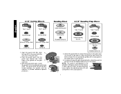
... operate the grinder with clamp lever in the closed . To remove the guard, open , rotate the guard (I 7 4-1/2" Cutting Wheels Sanding Discs 4-1/2" Sanding Flap Discs English Type 1 guard backing flange Type 1 guard backing flange abrasive cutting wheel diamond cutting wheel clamp nut clamp nut 1. You should be able to the diameter of time, the guard becomes P loose, tighten the adjusting screw (P) with a loose guard or the clamp lever in the groove on the gear case. 2. NOTE: The guard is pre-adjusted to rotate the guard by hand...
... operate the grinder with clamp lever in the closed . To remove the guard, open , rotate the guard (I 7 4-1/2" Cutting Wheels Sanding Discs 4-1/2" Sanding Flap Discs English Type 1 guard backing flange Type 1 guard backing flange abrasive cutting wheel diamond cutting wheel clamp nut clamp nut 1. You should be able to the diameter of time, the guard becomes P loose, tighten the adjusting screw (P) with a loose guard or the clamp lever in the groove on the gear case. 2. NOTE: The guard is pre-adjusted to rotate the guard by hand...
Instruction Manual
Page 9
... to use with the clamp lever in open position. Depress and release the paddle switch as shown on the tool warning label. The guard body should be used. Every unthreaded accessory must be rated for a circular saw and should not be unable to run while the switch is reconnected. Allow the grinder to rotate the guard by hand. MOUNTING AND REMOVING GUARD (D28110) O N 1. Do not operate grinder with Type 27 wheels designed...
... to use with the clamp lever in open position. Depress and release the paddle switch as shown on the tool warning label. The guard body should be used. Every unthreaded accessory must be rated for a circular saw and should not be unable to run while the switch is reconnected. Allow the grinder to rotate the guard by hand. MOUNTING AND REMOVING GUARD (D28110) O N 1. Do not operate grinder with Type 27 wheels designed...
Instruction Manual
Page 10
... the tool, turn - Ensure the switch is in damage to ensure that the tool is operating because damage to rotate the spindle further. To stop the tool, release the ON/OFF switch. CAUTION: Failure to properly seat the wheel before making any adjustments or removing or installing attachments or accessories. SPINDLE LOCK The spindle lock (C) is provided to ensure that the tool is released. Depress the spindle lock button and use applications. MOUNTING NON-HUBBED WHEELS CAUTION: Turn...
... the tool, turn - Ensure the switch is in damage to ensure that the tool is operating because damage to rotate the spindle further. To stop the tool, release the ON/OFF switch. CAUTION: Failure to properly seat the wheel before making any adjustments or removing or installing attachments or accessories. SPINDLE LOCK The spindle lock (C) is provided to ensure that the tool is released. Depress the spindle lock button and use applications. MOUNTING NON-HUBBED WHEELS CAUTION: Turn...
Instruction Manual
Page 11
... remove the wheel, depress the spindle lock button and loosen the threaded 1/8" WHEELS (3.31mm) clamp nut with a wrench. Allow the tool to reach full speed before placing wheel. 2. The open side of the spindle by pushing and twisting the flange before touching the tool to the work surface. 2. For deeper cutting with a Type 1 cut -off wheel, use of serious injury, limit the use a closed, Type 1 guard. Allow the tool to reach full speed before turning tool off...
... remove the wheel, depress the spindle lock button and loosen the threaded 1/8" WHEELS (3.31mm) clamp nut with a wrench. Allow the tool to reach full speed before placing wheel. 2. The open side of the spindle by pushing and twisting the flange before touching the tool to the work surface. 2. For deeper cutting with a Type 1 cut -off wheel, use of serious injury, limit the use a closed, Type 1 guard. Allow the tool to reach full speed before turning tool off...
Instruction Manual
Page 12
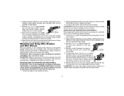
... material removal. WARNING: Do not use edge grinding/cutting wheels for surface grinding applications because these wheels are not designed to reach full speed before turning tool off . SURFACE FINISHING WITH SANDING FLAP DISCS 1. Allow the tool to withstand side pressures caused by hand. CAUTION: Proper guard must be reinstalled for grinding wheel, sanding flap disc, wire brush or wire wheel applications after sanding applications are snug. 5. H R 2. Tighten the clamp nut by bending. 5. Edge grinding wheels...
... material removal. WARNING: Do not use edge grinding/cutting wheels for surface grinding applications because these wheels are not designed to reach full speed before turning tool off . SURFACE FINISHING WITH SANDING FLAP DISCS 1. Allow the tool to withstand side pressures caused by hand. CAUTION: Proper guard must be reinstalled for grinding wheel, sanding flap disc, wire brush or wire wheel applications after sanding applications are snug. 5. H R 2. Tighten the clamp nut by bending. 5. Edge grinding wheels...
Instruction Manual
Page 13
... inch of the wire wheel or brush to fragment from the work surface, allowing the tool to work surface before turning tool off . 1. CAUTION: Wear work surface. 4. Before reconnecting the tool, turn the switch on may be used for removing rust, scale and paint, and for wire cup brushes. 4. Apply minimum pressure to operate at high speed. 3. Remove the tool from accessory wheel or cup. Apply minimum pressure to 10˚ angle between the tool and work surface. A Type...
... inch of the wire wheel or brush to fragment from the work surface, allowing the tool to work surface before turning tool off . 1. CAUTION: Wear work surface. 4. Before reconnecting the tool, turn the switch on may be used for removing rust, scale and paint, and for wire cup brushes. 4. Apply minimum pressure to operate at high speed. 3. Remove the tool from accessory wheel or cup. Apply minimum pressure to 10˚ angle between the tool and work surface. A Type...
Instruction Manual
Page 14
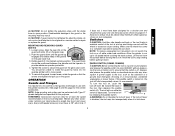
... clamp lever in open the guard latch, rotate the guard so that the tool is off . MOUNTING CUTTING WHEELS CAUTION: Turn off and unplug the tool before making any adjustments or removing or installing attachments or accessories. Place the wheel on the backing flange, centering the wheel on the gear N case hub. 3. Depress the spindle lock button and tighten clamp nut with the raised section (pilot) facing away from wheel breakage and wheel contact. Do not operate grinder...
... clamp lever in open the guard latch, rotate the guard so that the tool is off . MOUNTING CUTTING WHEELS CAUTION: Turn off and unplug the tool before making any adjustments or removing or installing attachments or accessories. Place the wheel on the backing flange, centering the wheel on the gear N case hub. 3. Depress the spindle lock button and tighten clamp nut with the raised section (pilot) facing away from wheel breakage and wheel contact. Do not operate grinder...
Instruction Manual
Page 15
... stop rotating before resetting the GFCI. This warranty gives you specific legal rights and you need assistance in certain states or provinces. 14 Remove the tool from the accumulation of motor and switch actuator using this tool could create an electrical shock or electrocution if not frequently cleaned out. English USING CUTTING WHEELS WARNING: Do not use . ALWAYS WEAR SAFETY GLASSES when cleaning or using clean, dry compressed air...
... stop rotating before resetting the GFCI. This warranty gives you specific legal rights and you need assistance in certain states or provinces. 14 Remove the tool from the accumulation of motor and switch actuator using this tool could create an electrical shock or electrocution if not frequently cleaned out. English USING CUTTING WHEELS WARNING: Do not use . ALWAYS WEAR SAFETY GLASSES when cleaning or using clean, dry compressed air...
Instruction Manual
Page 16
... the performance of your DEWALT Power Tool, Laser, or Nailer for any reason, you can return it within 90 days from the date of purchase with a receipt for a full refund - LATIN AMERICA: This warranty does not apply to the warranty, DEWALT tools are covered by our: 1 YEAR FREE SERVICE DEWALT will maintain the tool and replace worn parts caused by normal use, for free, any time during...
... the performance of your DEWALT Power Tool, Laser, or Nailer for any reason, you can return it within 90 days from the date of purchase with a receipt for a full refund - LATIN AMERICA: This warranty does not apply to the warranty, DEWALT tools are covered by our: 1 YEAR FREE SERVICE DEWALT will maintain the tool and replace worn parts caused by normal use, for free, any time during...
Instruction Manual
Page 52
the kit box configuration; the array of the tool. the "D" shaped air intake grill; and the array of lozenge-shaped humps on the surface of pyramids on the handgrip; Especificaciones D28402, D28402N Tensión de alimentación: 120 V AC/DC ( ) Consumo de corriente: 10 A Frecuencia...A 50/60 Hz 1 160 W 11 000/min DEWALT Industrial Tool Co., 701 East Joppa Road, Baltimore, MD 21286 (MAR06) Form No. 641881-00 D28110, D28112, D28402, D28402N Copyright © 2005, 2006 DEWALT The following are trademarks for one or more DEWALT power tools: the yellow and black color scheme;
the kit box configuration; the array of the tool. the "D" shaped air intake grill; and the array of lozenge-shaped humps on the surface of pyramids on the handgrip; Especificaciones D28402, D28402N Tensión de alimentación: 120 V AC/DC ( ) Consumo de corriente: 10 A Frecuencia...A 50/60 Hz 1 160 W 11 000/min DEWALT Industrial Tool Co., 701 East Joppa Road, Baltimore, MD 21286 (MAR06) Form No. 641881-00 D28110, D28112, D28402, D28402N Copyright © 2005, 2006 DEWALT The following are trademarks for one or more DEWALT power tools: the yellow and black color scheme;

Parts Diagram
Page 2
... SEAL 4 650916-01 BRUSH 2 623589-00 BRUSH SPRING 2 623591-00 CAP 2 593685-00 SCREW 2 623576-00 HANDLE ASSY. 1 945614-02 SWITCH 1 N055787 SEPARATOR 1 623619-00S PADDLE ASSY. 1 626006-00 CORD CLAMP 1 330019-03 SCREW 2 330005-01 PROTECTOR,CORD 1 636226-00 NUT 1 633257-00SV BACKING FLANGE 1 N342329 GUARD 1 397661-01 GUARD 1 625415-00 PLUG 1 625323-00 LOCK-ON BUTTON 1 562210-00 SPRING 1 330072-98 CORD/8FT/18-2SJ...
... SEAL 4 650916-01 BRUSH 2 623589-00 BRUSH SPRING 2 623591-00 CAP 2 593685-00 SCREW 2 623576-00 HANDLE ASSY. 1 945614-02 SWITCH 1 N055787 SEPARATOR 1 623619-00S PADDLE ASSY. 1 626006-00 CORD CLAMP 1 330019-03 SCREW 2 330005-01 PROTECTOR,CORD 1 636226-00 NUT 1 633257-00SV BACKING FLANGE 1 N342329 GUARD 1 397661-01 GUARD 1 625415-00 PLUG 1 625323-00 LOCK-ON BUTTON 1 562210-00 SPRING 1 330072-98 CORD/8FT/18-2SJ...

Parts Diagram
Page 3
...76 77 78 79 80 81 82 83 84 85 86 87 88 92 93 96 800 800 Part Number 629107-00 628885-00 626891-00 604484-00 623564-00 330003-60 623617-00 623580-00 623613-...583534-00 30301914-01 Parts List for D28402 Type 1 Description Qty Required NAMEPLATE 1 ID LABEL 1 WARNING LABEL 1 NUT 1 PINION 1 BEARING 1 FELT SEAL 1 BRG. RETAINER 1 SLINGER 1 BALL BEARING 1 BEARING CUP 1 FIELD 1 FAN BAFFLE 1 SCREW 4 GASKET 1 SLEEVE,RUBBER 1 GEAR CASE COVER 1 SCREW 4 SCREW 1 TERMINAL 2 WRENCH 1 SIDE HANDLE 1 O-RING 1 O-RING 1 SPINDLE LOCK BUTTON 1 GREASE 1 GREASE ...
...76 77 78 79 80 81 82 83 84 85 86 87 88 92 93 96 800 800 Part Number 629107-00 628885-00 626891-00 604484-00 623564-00 330003-60 623617-00 623580-00 623613-...583534-00 30301914-01 Parts List for D28402 Type 1 Description Qty Required NAMEPLATE 1 ID LABEL 1 WARNING LABEL 1 NUT 1 PINION 1 BEARING 1 FELT SEAL 1 BRG. RETAINER 1 SLINGER 1 BALL BEARING 1 BEARING CUP 1 FIELD 1 FAN BAFFLE 1 SCREW 4 GASKET 1 SLEEVE,RUBBER 1 GEAR CASE COVER 1 SCREW 4 SCREW 1 TERMINAL 2 WRENCH 1 SIDE HANDLE 1 O-RING 1 O-RING 1 SPINDLE LOCK BUTTON 1 GREASE 1 GREASE ...

Parts Diagram
Page 4
Item Number 800 800 836 846 846 856 856 856 861 Part Number 429954-00 429954-01 233804-36 5140030-98 625415-00 N342331 643772-00 DW4514 651196-00 Parts List for D28402 Type 1 Description Qty Required GREASE, 7LBS 1 GREASE,1 LB. 1 TORX DRIVER 1 SHIM 1 PLUG 1 GUARD 1 GUARD 1 4-1/2X1/4 METL 1 KITBOX 1 DEWALT ELECTRIC POWER TOOLS
Item Number 800 800 836 846 846 856 856 856 861 Part Number 429954-00 429954-01 233804-36 5140030-98 625415-00 N342331 643772-00 DW4514 651196-00 Parts List for D28402 Type 1 Description Qty Required GREASE, 7LBS 1 GREASE,1 LB. 1 TORX DRIVER 1 SHIM 1 PLUG 1 GUARD 1 GUARD 1 4-1/2X1/4 METL 1 KITBOX 1 DEWALT ELECTRIC POWER TOOLS


