Instruction Manual
Page 2
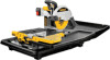
... rigorous use on jobsites and throughout the industry. from drills to sanders to make sure that it leaves the factory to grinders - Every tool is the result of every tool in the line - DEWALT Built Jobsite Tough WE GUARANTEE IT. English IF YOU HAVE ANY QUESTIONS OR COMMENTS ABOUT THIS OR ANY DEWALT TOOL, CALL US TOLL FREE AT: 1-800-4-DEWALT...
... rigorous use on jobsites and throughout the industry. from drills to sanders to make sure that it leaves the factory to grinders - Every tool is the result of every tool in the line - DEWALT Built Jobsite Tough WE GUARANTEE IT. English IF YOU HAVE ANY QUESTIONS OR COMMENTS ABOUT THIS OR ANY DEWALT TOOL, CALL US TOLL FREE AT: 1-800-4-DEWALT...
Instruction Manual
Page 3
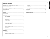
English TABLE OF CONTENTS IMPORTANT SAFETY INSTRUCTIONS FOR ALL TOOLS 2 GROUNDING INSTRUCTIONS 2 ADDITIONAL SAFETY RULES FOR WET TILE SAWS 3 QUICK START GUIDE 4 FEATURES ...6 ASSEMBLY ...6 SPECIFICATIONS ...7 OPERATION ...7 TOOL PLACEMENT 7 MOTOR ...7 ON/OFF SWITCH 7 WATER NOZZLES 7 CUTTING WHEEL ALIGNMENT 7 CUTTING WHEEL DEPTH 7 MAKING A CUT 7 LOCKING THE CUTTING CART 8 TYPES OF CUT 8 ADJUSTMENTS 9 MAINTENANCE...10 BRUSHES 10 TRANSPORTATION AND STORAGE 10 CLEANING 10 LUBRICATION 10 REPAIRS ...10 ACCESSORIES ...10 WARRANTY ...10 TROUBLESHOOTING GUIDE 11 1
English TABLE OF CONTENTS IMPORTANT SAFETY INSTRUCTIONS FOR ALL TOOLS 2 GROUNDING INSTRUCTIONS 2 ADDITIONAL SAFETY RULES FOR WET TILE SAWS 3 QUICK START GUIDE 4 FEATURES ...6 ASSEMBLY ...6 SPECIFICATIONS ...7 OPERATION ...7 TOOL PLACEMENT 7 MOTOR ...7 ON/OFF SWITCH 7 WATER NOZZLES 7 CUTTING WHEEL ALIGNMENT 7 CUTTING WHEEL DEPTH 7 MAKING A CUT 7 LOCKING THE CUTTING CART 8 TYPES OF CUT 8 ADJUSTMENTS 9 MAINTENANCE...10 BRUSHES 10 TRANSPORTATION AND STORAGE 10 CLEANING 10 LUBRICATION 10 REPAIRS ...10 ACCESSORIES ...10 WARRANTY ...10 TROUBLESHOOTING GUIDE 11 1
Instruction Manual
Page 4
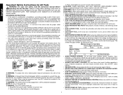
.... Follow instructions for recommended accessories. Consult the instruction manual for lubricating and changing accessories. • DISCONNECT TOOLS before servicing; When servicing this tool, use the next heavier gage. This tool is in . • USE RECOMMENDED ACCESSORIES. ADAPTER SHOWN IN SKETCHES B and C IS NOT FOR USE IN CANADA. When using an extension cord, be avoided. • ALWAYS USE SAFETY GLASSES. CAUTION: WHEN SERVICING USE ONLY IDENTICAL REPLACEMENT PARTS. Don't force tool or attachment to the tool, fire...
.... Follow instructions for recommended accessories. Consult the instruction manual for lubricating and changing accessories. • DISCONNECT TOOLS before servicing; When servicing this tool, use the next heavier gage. This tool is in . • USE RECOMMENDED ACCESSORIES. ADAPTER SHOWN IN SKETCHES B and C IS NOT FOR USE IN CANADA. When using an extension cord, be avoided. • ALWAYS USE SAFETY GLASSES. CAUTION: WHEN SERVICING USE ONLY IDENTICAL REPLACEMENT PARTS. Don't force tool or attachment to the tool, fire...
Instruction Manual
Page 5
... moving parts, binding of moving the workpiece or changing settings. • To reduce risk of electrocution, keep all clamp handles and knobs are read and understood. • Use safety equipment. Be sure all connections dry and off the tool and wait for the dust exposure. Tighten arbor screw securely. • DO - Keep the motor air slots free of the saw without cover in the receptacle. Keep hands out...
... moving parts, binding of moving the workpiece or changing settings. • To reduce risk of electrocution, keep all clamp handles and knobs are read and understood. • Use safety equipment. Be sure all connections dry and off the tool and wait for the dust exposure. Tighten arbor screw securely. • DO - Keep the motor air slots free of the saw without cover in the receptacle. Keep hands out...
Instruction Manual
Page 6
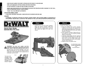
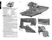
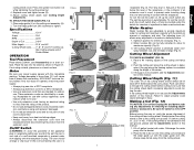
... LOCATIONS. Quick Start Guide D24000 Wet Tile Saw Step 1 1. WARNING: For your own safety, read the instruction manual before operating the wet tile saw . Have damaged cords replaced by an authorized service center. Using the smaller Allen wrench supplied, loosen (do not remove) the screw on the cutting wheel cover. Press the spindle lock button while tightening the cutting wheel nut. Install the cutting wheel with hex wrench provided. d. ON CUTTING WHEEL COVER CAUTION: PROPERLY SECURE COVER WITH BOTH SCREWS BEFORE USE. FIG...
... LOCATIONS. Quick Start Guide D24000 Wet Tile Saw Step 1 1. WARNING: For your own safety, read the instruction manual before operating the wet tile saw . Have damaged cords replaced by an authorized service center. Using the smaller Allen wrench supplied, loosen (do not remove) the screw on the cutting wheel cover. Press the spindle lock button while tightening the cutting wheel nut. Install the cutting wheel with hex wrench provided. d. ON CUTTING WHEEL COVER CAUTION: PROPERLY SECURE COVER WITH BOTH SCREWS BEFORE USE. FIG...
Instruction Manual
Page 7
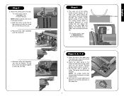
... water. Place the saw . Attach the water pump to Adjustments in the Instruction Manual. Turn saw on the water line. 5 3/16" (5MM) D English NOTE: Make sure the cart lock is desired, use the flow restrictor on . a. Place the rear roller assembly onto the round rail. c. Step 4 4. For further details, refer to the water line and insert pump power cord into the socket...
... water. Place the saw . Attach the water pump to Adjustments in the Instruction Manual. Turn saw on the water line. 5 3/16" (5MM) D English NOTE: Make sure the cart lock is desired, use the flow restrictor on . a. Place the rear roller assembly onto the round rail. c. Step 4 4. For further details, refer to the water line and insert pump power cord into the socket...
Instruction Manual
Page 8
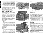
... the drain plug. Insert the pump power cord into the socket (Q). 8. TO ATTACH CUTTING WHEEL (FIG. 5) 1. Place saw frame assembly. 3. Place the threaded fitting onto the water pump (N). Install rear water attachment (G). 9. Install cutting cart water attachment (I . Press spindle lock button. Place the water pump in Figure 2. 6. A On/Off switch I ). Using the smaller Allen wrench supplied, loosen (do not remove) the screw (R) on a stable surface. 2. Remove outer flange (T). 3. Open...
... the drain plug. Insert the pump power cord into the socket (Q). 8. TO ATTACH CUTTING WHEEL (FIG. 5) 1. Place saw frame assembly. 3. Place the threaded fitting onto the water pump (N). Install rear water attachment (G). 9. Install cutting cart water attachment (I . Press spindle lock button. Place the water pump in Figure 2. 6. A On/Off switch I ). Using the smaller Allen wrench supplied, loosen (do not remove) the screw (R) on a stable surface. 2. Remove outer flange (T). 3. Open...
Instruction Manual
Page 9
... the spindle lock button (U) while tightening the cutting wheel nut. 4. Place edge guide (J) on automatically. If not using and replace if damaged. • Do not abuse extension cords and do not yank on a level surface. All DEWALT tools are adjustable to be at least 3/16" (5mm) below the level of this manual. Failure to tighten. If the cutting wheel is used, to prevent water traveling along the length of Cut 3-3/4" Miter Angels...
... the spindle lock button (U) while tightening the cutting wheel nut. 4. Place edge guide (J) on automatically. If not using and replace if damaged. • Do not abuse extension cords and do not yank on a level surface. All DEWALT tools are adjustable to be at least 3/16" (5mm) below the level of this manual. Failure to tighten. If the cutting wheel is used, to prevent water traveling along the length of Cut 3-3/4" Miter Angels...
Instruction Manual
Page 10
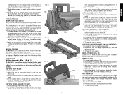
... a piece of the cutting wheel. Q Z L-CUTS An L-cut indicator will need to the radius of tile for electrical outlets and for making any adjustments or removing or installing attachments or accessories. C D LL DD PLUNGE CUTS Plunge cuts are three locking positions for air conditioner registers. 1. With one hand on the plunge handle (C) and one of water from the water pump completely covers the cutting wheel. English 3. After the cutting wheel stops, remove the...
... a piece of the cutting wheel. Q Z L-CUTS An L-cut indicator will need to the radius of tile for electrical outlets and for making any adjustments or removing or installing attachments or accessories. C D LL DD PLUNGE CUTS Plunge cuts are three locking positions for air conditioner registers. 1. With one hand on the plunge handle (C) and one of water from the water pump completely covers the cutting wheel. English 3. After the cutting wheel stops, remove the...
Instruction Manual
Page 11
... the bevel pointer (DD) to 45˚. 2. Adjust depth of the saw and adjust the head of the mark without overcutting. 7. Turn the tile over. Turn off and unplug the tool before adjustment is adjustable to the center of adjustment. 2. MITER CUTS: 22.5˚ AND 45˚ Miter cuts are used multiple times before making any adjustments or removing or installing attachments or accessories. The cutting head of cut indicator can be used for the cutting head...
... the bevel pointer (DD) to 45˚. 2. Adjust depth of the saw and adjust the head of the mark without overcutting. 7. Turn the tile over. Turn off and unplug the tool before adjustment is adjustable to the center of adjustment. 2. MITER CUTS: 22.5˚ AND 45˚ Miter cuts are used multiple times before making any adjustments or removing or installing attachments or accessories. The cutting head of cut indicator can be used for the cutting head...
Instruction Manual
Page 12
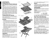
... let any adjustments or removing or installing attachments or accessories. Clean the water pan by unplugging tool, removing the brush cap (OO) and withdrawing the brush assembly. Also, do not use with your tool are available at no questions asked. CAUTION: The use , for free, any other qualified service organizations, always using identical replacement parts. no load) for a thorough cleaning and inspection. Use only identical DEWALT brushes. The edge guide (J) and the cutting cart...
... let any adjustments or removing or installing attachments or accessories. Clean the water pan by unplugging tool, removing the brush cap (OO) and withdrawing the brush assembly. Also, do not use with your tool are available at no questions asked. CAUTION: The use , for free, any other qualified service organizations, always using identical replacement parts. no load) for a thorough cleaning and inspection. Use only identical DEWALT brushes. The edge guide (J) and the cutting cart...
Instruction Manual
Page 13
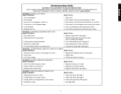
...and replace fuse or reset circuit breaker. 5. Arbor loose 2. Use edge guide. 11 switch on cutting wheel 5. Have brushes replaced by authorized service center. 6. Build up . 5. Replace with clean water to fence 3. Tighten arbor 3. Stand or bench on stand. 2. Check and adjust. See page 9. 3. Turn cutting wheel around. TROUBLE! Damaged saw . 2. Reposition water pan on uneven floor 3. Cutting wheel is not square to dislodge the impeller 3. English Troubleshooting Guide BE SURE TO FOLLOW SAFETY RULES AND INSTRUCTIONS MANY COMMON PROBLEMS...
...and replace fuse or reset circuit breaker. 5. Arbor loose 2. Use edge guide. 11 switch on cutting wheel 5. Have brushes replaced by authorized service center. 6. Build up . 5. Replace with clean water to fence 3. Tighten arbor 3. Stand or bench on stand. 2. Check and adjust. See page 9. 3. Turn cutting wheel around. TROUBLE! Damaged saw . 2. Reposition water pan on uneven floor 3. Cutting wheel is not square to dislodge the impeller 3. English Troubleshooting Guide BE SURE TO FOLLOW SAFETY RULES AND INSTRUCTIONS MANY COMMON PROBLEMS...
Parts Diagram
Page 2
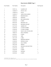
....com for D24000 Type 1 Description Qty Required NAMEPLATE 1 FIELD CASE 1 FIELD 1 ARMATURE & BRGS 1 BEARING,BALL 1 BEARING 1 RETAINING RING 1 SCREW 5 BEARING CUP 1 BUSHING,STR.RLF 1 ARBOR NUT 1 CLAMP WASHER 1 CLAMP WASHER 1 GEAR CASE COVER ASSY. 1 BALL BEARING 1 SCREW 16 ARM 1 LABEL 1 BEARING,NEEDLE 1 SPINDLE LOCK 1 FELT WIPER 1 SPRING 2 SPINDLE LOCK BUTTON 1 LINER 1 SCREW 4 HANDLE 1 SCREW 17 COPYRIGHT© 2005. Page 1 All Rights Reserved. Parts list, pricing, and availability subject to change. Item Number 1 2 3 4 5 6 7 10 12...
....com for D24000 Type 1 Description Qty Required NAMEPLATE 1 FIELD CASE 1 FIELD 1 ARMATURE & BRGS 1 BEARING,BALL 1 BEARING 1 RETAINING RING 1 SCREW 5 BEARING CUP 1 BUSHING,STR.RLF 1 ARBOR NUT 1 CLAMP WASHER 1 CLAMP WASHER 1 GEAR CASE COVER ASSY. 1 BALL BEARING 1 SCREW 16 ARM 1 LABEL 1 BEARING,NEEDLE 1 SPINDLE LOCK 1 FELT WIPER 1 SPRING 2 SPINDLE LOCK BUTTON 1 LINER 1 SCREW 4 HANDLE 1 SCREW 17 COPYRIGHT© 2005. Page 1 All Rights Reserved. Parts list, pricing, and availability subject to change. Item Number 1 2 3 4 5 6 7 10 12...
Parts Diagram
Page 3
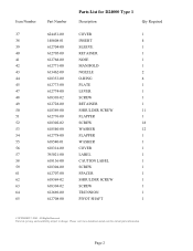
...dewaltservicenet.com for D24000 Type 1 Description Qty Required COVER 1 INSERT 4 SLEEVE 1 RETAINER 1 NOSE 1 MANIFOLD 1 NOZZLE 2 O-RING 4 PLATE 1 LEVER 1 SCREW 1 RETAINER 1 SHOULDER SCREW 11 FLAPPER 1 SCREW 18 WASHER 12 FLAPPER 1 WASHER 1 COVER 1 LABEL 1 CAUTION LABEL 1 SCREW 1 SPACER 1 SHOULDER SCREW 1 SCREW 1 TRUNNION 1 PIVOT SHAFT 1 COPYRIGHT© 2005. Item Number 37 38 ... 618369-02 618304-02 612669-00 612708-00 Parts List for current parts information. All Rights Reserved. Parts list, pricing, and availability subject to change.
...dewaltservicenet.com for D24000 Type 1 Description Qty Required COVER 1 INSERT 4 SLEEVE 1 RETAINER 1 NOSE 1 MANIFOLD 1 NOZZLE 2 O-RING 4 PLATE 1 LEVER 1 SCREW 1 RETAINER 1 SHOULDER SCREW 11 FLAPPER 1 SCREW 18 WASHER 12 FLAPPER 1 WASHER 1 COVER 1 LABEL 1 CAUTION LABEL 1 SCREW 1 SPACER 1 SHOULDER SCREW 1 SCREW 1 TRUNNION 1 PIVOT SHAFT 1 COPYRIGHT© 2005. Item Number 37 38 ... 618369-02 618304-02 612669-00 612708-00 Parts List for current parts information. All Rights Reserved. Parts list, pricing, and availability subject to change.
Parts Diagram
Page 4
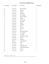
Please visit www.dewaltservicenet.com for D24000 Type 1 Description Qty Required PIVOT SHAFT 1 SPACER 2 SPRING 1 BUSHING 4 SET SCREW 4 BEVEL KNOB 1 KNOB 1 SET SCREW 1 BRACKET 1 KNOB 1 WASHER 2 BOLT 1 BUSHING 1 PIN 1 RETAINING RING 1 SET SCREW 1 COLUMN 1 WARNING LABEL 1 PLATE 1 WRENCH 1 HEX WRENCH 1 CLIP 1 CLIP 1 SUPPORT ARM 1 SHOULDER SCREW 3 PLATE 1 PLATE 1 COPYRIGHT© 2005. Parts list, pricing, and availability subject to change. All Rights Reserved. Page 3 Item Number 66 67 68 69 70 71 74 75 76 77 78 79...
Please visit www.dewaltservicenet.com for D24000 Type 1 Description Qty Required PIVOT SHAFT 1 SPACER 2 SPRING 1 BUSHING 4 SET SCREW 4 BEVEL KNOB 1 KNOB 1 SET SCREW 1 BRACKET 1 KNOB 1 WASHER 2 BOLT 1 BUSHING 1 PIN 1 RETAINING RING 1 SET SCREW 1 COLUMN 1 WARNING LABEL 1 PLATE 1 WRENCH 1 HEX WRENCH 1 CLIP 1 CLIP 1 SUPPORT ARM 1 SHOULDER SCREW 3 PLATE 1 PLATE 1 COPYRIGHT© 2005. Parts list, pricing, and availability subject to change. All Rights Reserved. Page 3 Item Number 66 67 68 69 70 71 74 75 76 77 78 79...
Parts Diagram
Page 5
Parts list, pricing, and availability subject to change. Page 4 Please visit www.dewaltservicenet.com for D24000 Type 1 Description Qty Required LABEL 1 COVER 1 END CAP 1 SWITCH 1 SWITCH PLATE 1 SWITCH BEZEL 1 ENCLOSURE 1 SCREW 28 COVER 1 ENCLOSURE 1 CORD 1 TERMINAL,MALE 4 TERMINAL,FEMALE 6 BUSHING 5 CORD 1 TERMINAL 2 CORD & PLUG 1 WIRE CLIP 1 SCREW,M4-U0 3 SCREW 2 CLAMP 4 ELBOW 1 FRAME 1 PLATE 1 PLATE 2 SHOULDER SCREW 4 SCREW 2 COPYRIGHT© 2005. All Rights Reserved. Item Number 95 96 97 98 99 100 101...
Parts list, pricing, and availability subject to change. Page 4 Please visit www.dewaltservicenet.com for D24000 Type 1 Description Qty Required LABEL 1 COVER 1 END CAP 1 SWITCH 1 SWITCH PLATE 1 SWITCH BEZEL 1 ENCLOSURE 1 SCREW 28 COVER 1 ENCLOSURE 1 CORD 1 TERMINAL,MALE 4 TERMINAL,FEMALE 6 BUSHING 5 CORD 1 TERMINAL 2 CORD & PLUG 1 WIRE CLIP 1 SCREW,M4-U0 3 SCREW 2 CLAMP 4 ELBOW 1 FRAME 1 PLATE 1 PLATE 2 SHOULDER SCREW 4 SCREW 2 COPYRIGHT© 2005. All Rights Reserved. Item Number 95 96 97 98 99 100 101...
Parts Diagram
Page 6
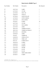
Parts list, pricing, and availability subject to change. Page 5 Please visit www.dewaltservicenet.com for D24000 Type 1 Description Qty Required FOOT 4 RAIL 1 LINER 1 CAP 1 CAP 1 GUIDE ROD 1 BLOCK 4 CYLINDER 1 SCREW 1 RETAINING RING 1 SCREW 8 RAIL 1 SCREW 4 BRACKET 2 SCREW 2 BUSHING 2 SCREW 1 SHOULDER SCREW 4 CART 1 CART 1 WARNING LABEL 1 LABEL 1 WARNING LABEL 2 ROLLER GUIDE 3 SPACER 6 BALL BEARING 9 SCREW 3 COPYRIGHT© 2005. Item Number 129 131 132 133 134 136 137...
Parts list, pricing, and availability subject to change. Page 5 Please visit www.dewaltservicenet.com for D24000 Type 1 Description Qty Required FOOT 4 RAIL 1 LINER 1 CAP 1 CAP 1 GUIDE ROD 1 BLOCK 4 CYLINDER 1 SCREW 1 RETAINING RING 1 SCREW 8 RAIL 1 SCREW 4 BRACKET 2 SCREW 2 BUSHING 2 SCREW 1 SHOULDER SCREW 4 CART 1 CART 1 WARNING LABEL 1 LABEL 1 WARNING LABEL 2 ROLLER GUIDE 3 SPACER 6 BALL BEARING 9 SCREW 3 COPYRIGHT© 2005. Item Number 129 131 132 133 134 136 137...
Parts Diagram
Page 7
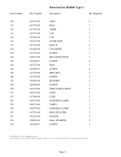
Page 6 Parts list, pricing, and availability subject to change. All Rights Reserved. Please visit www.dewaltservicenet.com for D24000 Type 1 Description Qty Required SHAFT 3 STOP NUT 6 CYLINDER 1 ROLLER 3 SPACER 3 SCREW 3 PLATE 1 SCALE 1 BRACKET 1 ROD 1 SCREW 1 BRUSH 1 GUTTER 2 SHOULDER SCREW 12 DISC 1 STOP 1 COLLECTOR 1 EDGE GUIDE 1 GUIDE 1 KNOB 2 CLAMPING PLATE 1 TUBING 1 VALVE 1 PUMP 1 FITTING 1 PAN 1 EXTENSION 1 COPYRIGHT© 2005. Item Number 160 161 162 164 165 166 167 169 171 172 173 174...
Page 6 Parts list, pricing, and availability subject to change. All Rights Reserved. Please visit www.dewaltservicenet.com for D24000 Type 1 Description Qty Required SHAFT 3 STOP NUT 6 CYLINDER 1 ROLLER 3 SPACER 3 SCREW 3 PLATE 1 SCALE 1 BRACKET 1 ROD 1 SCREW 1 BRUSH 1 GUTTER 2 SHOULDER SCREW 12 DISC 1 STOP 1 COLLECTOR 1 EDGE GUIDE 1 GUIDE 1 KNOB 2 CLAMPING PLATE 1 TUBING 1 VALVE 1 PUMP 1 FITTING 1 PAN 1 EXTENSION 1 COPYRIGHT© 2005. Item Number 160 161 162 164 165 166 167 169 171 172 173 174...
Parts Diagram
Page 8
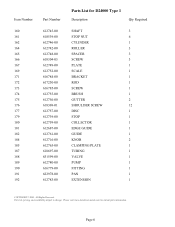
All Rights Reserved. Page 7 Parts list, pricing, and availability subject to change. Please visit www.dewaltservicenet.com for D24000 Type 1 Description Qty Required STOPPER 1 TRAY 1 BEVEL POINTER 1 SCREW 1 SCREW 4 SCREW 2 WING NUT 1 SET SCREW 1 COVER 1 SCREW 2 LEAD 1 LEAD ASSY. 1 TERMINAL BLOCK 1 ROPE 1 COVER 3 SCREW 2 EXTENSION 1 SCALE 1 GUIDE PIN 2 NUT 2 INSERT 1 DISC 1 SCREW 4 WASHER 2 PIN 1 LATCH 1 RETAINING CLIP 1 COPYRIGHT© 2005. Item Number 193 194 195 196 197 198 199 200 203 204 205...
All Rights Reserved. Page 7 Parts list, pricing, and availability subject to change. Please visit www.dewaltservicenet.com for D24000 Type 1 Description Qty Required STOPPER 1 TRAY 1 BEVEL POINTER 1 SCREW 1 SCREW 4 SCREW 2 WING NUT 1 SET SCREW 1 COVER 1 SCREW 2 LEAD 1 LEAD ASSY. 1 TERMINAL BLOCK 1 ROPE 1 COVER 3 SCREW 2 EXTENSION 1 SCALE 1 GUIDE PIN 2 NUT 2 INSERT 1 DISC 1 SCREW 4 WASHER 2 PIN 1 LATCH 1 RETAINING CLIP 1 COPYRIGHT© 2005. Item Number 193 194 195 196 197 198 199 200 203 204 205...
Parts Diagram
Page 9
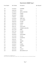
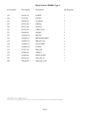
...-31 5140024-32 5140024-33 5140024-34 627857-00 619840-00 612688-00 635225-00 790206-00 Parts List for current parts information. Parts list, pricing, and availability subject to change. Please visit www.dewaltservicenet.com for D24000 Type 1 Description Qty Required SCREW 1 O-RING 1 WASHER 2 SPRING 1 SLEEVE 1 CORD CLIP 1 INSERT 4 BRUSH 2 BRUSH HOLDER 2 BRUSH CAP 2 SET SCREW 2 SCREW 2 ROLLER 3 SHIELD 1 EDGE GUIDE 1 GFCI PLUG 1 GREASE, 6 OZ. 1 COPYRIGHT© 2005. All Rights Reserved.
...-31 5140024-32 5140024-33 5140024-34 627857-00 619840-00 612688-00 635225-00 790206-00 Parts List for current parts information. Parts list, pricing, and availability subject to change. Please visit www.dewaltservicenet.com for D24000 Type 1 Description Qty Required SCREW 1 O-RING 1 WASHER 2 SPRING 1 SLEEVE 1 CORD CLIP 1 INSERT 4 BRUSH 2 BRUSH HOLDER 2 BRUSH CAP 2 SET SCREW 2 SCREW 2 ROLLER 3 SHIELD 1 EDGE GUIDE 1 GFCI PLUG 1 GREASE, 6 OZ. 1 COPYRIGHT© 2005. All Rights Reserved.


