Owner's Manual
Page 7
...PM CD/DVD Drive 114 Removing a CD/DVD Drive 114 Installing a CD/DVD Drive 116 Liquid Cooling Assembly 119 Removing the Liquid Cooling Assembly 119 Installing the Liquid Cooling Assembly 121 Processor 122 Removing the Processor 122 Installing the Processor 123 Battery 125 Replacing the Battery 125 ... Your Computer 143 Computer, Keyboard, and Monitor 143 Mouse 144 Floppy Drive 144 CDs and DVDs 144 Dell Hardware Warranty Support Policy (U.S. Only 145 Definition of "Dell-Installed" Software and Peripherals 145 Definition of "Third-Party" Software and Peripherals 145 Contents 7
...PM CD/DVD Drive 114 Removing a CD/DVD Drive 114 Installing a CD/DVD Drive 116 Liquid Cooling Assembly 119 Removing the Liquid Cooling Assembly 119 Installing the Liquid Cooling Assembly 121 Processor 122 Removing the Processor 122 Installing the Processor 123 Battery 125 Replacing the Battery 125 ... Your Computer 143 Computer, Keyboard, and Monitor 143 Mouse 144 Floppy Drive 144 CDs and DVDs 144 Dell Hardware Warranty Support Policy (U.S. Only 145 Definition of "Dell-Installed" Software and Peripherals 145 Definition of "Third-Party" Software and Peripherals 145 Contents 7
Owner's Manual
Page 80
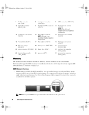
... (RTCRST) 20 battery socket (BATTERY) 21 password jumper (PASSWORD) 22 power connector (POWER2) 23 floppy drive (DSKT) 24 card cage fan connector (FAN_CAGE) 25 liquid cooling assembly (TEC_PUMP) 26 processor (CPU) 27 processor fan connector (FAN1_CPU) Memory You can increase your computer memory by your computer, see "Memory" on page 129...
... (RTCRST) 20 battery socket (BATTERY) 21 password jumper (PASSWORD) 22 power connector (POWER2) 23 floppy drive (DSKT) 24 card cage fan connector (FAN_CAGE) 25 liquid cooling assembly (TEC_PUMP) 26 processor (CPU) 27 processor fan connector (FAN1_CPU) Memory You can increase your computer memory by your computer, see "Memory" on page 129...
Owner's Manual
Page 110
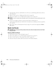
... "Removing the Drive Panel" on page 127). NOTICE: To connect a network cable, first plug the cable in to avoid blocking airflow between the fan and cooling vents. 8 Replace the drive panel (see "Replacing the Drive Panel" on page 106). 9 Replace the computer cover (see "Replacing the Computer Cover" on page 105...
... "Removing the Drive Panel" on page 127). NOTICE: To connect a network cable, first plug the cable in to avoid blocking airflow between the fan and cooling vents. 8 Replace the drive panel (see "Replacing the Drive Panel" on page 106). 9 Replace the computer cover (see "Replacing the Computer Cover" on page 105...
Owner's Manual
Page 114
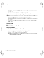
... Friday, October 27, 2006 4:02 PM 8 Check all cable connections and fold cables out of the way to avoid blocking airflow between the fan and cooling vents. 9 Replace the drive panel (see "Replacing the Drive Panel" on page 106). 10 Replace the computer cover (see "Removing the Drive Panel" on page...
... Friday, October 27, 2006 4:02 PM 8 Check all cable connections and fold cables out of the way to avoid blocking airflow between the fan and cooling vents. 9 Replace the drive panel (see "Replacing the Drive Panel" on page 106). 10 Replace the computer cover (see "Removing the Drive Panel" on page...
Owner's Manual
Page 118
... drive. book.book Page 118 Friday, October 27, 2006 4:02 PM 8 Attach the power and data cables to avoid blocking airflow between the fan and cooling vents. 10 Replace the drive panel (see "Replacing the Drive Panel" on page 106). 11 Replace the computer cover (see "Replacing the Computer Cover" on...
... drive. book.book Page 118 Friday, October 27, 2006 4:02 PM 8 Attach the power and data cables to avoid blocking airflow between the fan and cooling vents. 10 Replace the drive panel (see "Replacing the Drive Panel" on page 106). 11 Replace the computer cover (see "Replacing the Computer Cover" on...
Owner's Manual
Page 119
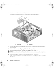
Liquid Cooling Assembly CAUTION: Before you perform this procedure, follow the safety instructions located in "Before You Begin" on page 75. 2 ...the CD/DVD drive(s) from the computer. Be sure that the heat sink has had sufficient time to cool before you intend to remove a CD/DVD drive see "Removing the Computer Cover" on page 76). Removing the Liquid... Cooling Assembly 1 Follow the procedures in the Product Information Guide. CAUTION: The processor heat sink can get very hot ...
Liquid Cooling Assembly CAUTION: Before you perform this procedure, follow the safety instructions located in "Before You Begin" on page 75. 2 ...the CD/DVD drive(s) from the computer. Be sure that the heat sink has had sufficient time to cool before you intend to remove a CD/DVD drive see "Removing the Computer Cover" on page 76). Removing the Liquid... Cooling Assembly 1 Follow the procedures in the Product Information Guide. CAUTION: The processor heat sink can get very hot ...
Owner's Manual
Page 120
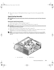
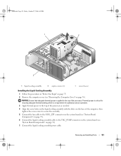
...PM 5 Remove any full-length expansion cards (see "Removing PCI and PCI Express Cards" on page 85). 6 Disconnect the liquid cooling assembly power cable. 7 Disconnect the liquid cooling assembly cable from the TEC_PUMP connector on the system board (see "System Board Components" on page 79). 1 2 1 power ... the fan cable from the FAN1_CPU connector on the system board (see "System Board Components" on its side to the liquid cooling assembly. When you remove the liquid cooling assembly, lay it aside. 120 Removing and Installing Parts NOTICE: The processor heat sink is not captive.
...PM 5 Remove any full-length expansion cards (see "Removing PCI and PCI Express Cards" on page 85). 6 Disconnect the liquid cooling assembly power cable. 7 Disconnect the liquid cooling assembly cable from the TEC_PUMP connector on the system board (see "System Board Components" on page 79). 1 2 1 power ... the fan cable from the FAN1_CPU connector on the system board (see "System Board Components" on its side to the liquid cooling assembly. When you remove the liquid cooling assembly, lay it aside. 120 Removing and Installing Parts NOTICE: The processor heat sink is not captive.
Owner's Manual
Page 121
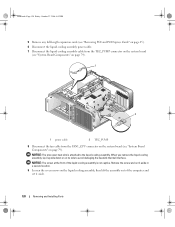
... 1 Follow the procedures in "Before You Begin" on page 75. 2 Remove the computer cover (see "System Board Components" on page 79). 6 Connect the liquid cooling assembly cable to the top of the computer, then tighten the seven screws to secure the assembly. 5 Connect the fan cable to the FAN1_CPU connector ... grease is critical for optimal processor operation. 3 Apply thermal grease to the top of the processor, as needed. 4 Align the screw holes on the liquid cooling assembly with the holes on page 79). 7 Connect the liquid...
... 1 Follow the procedures in "Before You Begin" on page 75. 2 Remove the computer cover (see "System Board Components" on page 79). 6 Connect the liquid cooling assembly cable to the top of the computer, then tighten the seven screws to secure the assembly. 5 Connect the fan cable to the FAN1_CPU connector ... grease is critical for optimal processor operation. 3 Apply thermal grease to the top of the processor, as needed. 4 Align the screw holes on the liquid cooling assembly with the holes on page 79). 7 Connect the liquid...
Owner's Manual
Page 122
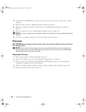
...the POWER1 and POWER2 connectors (see "System Board Components" on page 79) on the system board. 4 Remove the liquid cooling assembly (see "Removing the Liquid Cooling Assembly" on page 119). 5 Push down and out on the socket release lever. 122 Removing and Installing Parts For ...Removing the Processor 1 Follow the procedures in the Product Information Guide. Only)" on page 87). 11 Close the computer cover (see "Dell Hardware Warranty Support Policy (U.S. Performing these steps incorrectly could damage your computer and devices to electrical outlets, and turn them on page ...
...the POWER1 and POWER2 connectors (see "System Board Components" on page 79) on the system board. 4 Remove the liquid cooling assembly (see "Removing the Liquid Cooling Assembly" on page 119). 5 Push down and out on the socket release lever. 122 Removing and Installing Parts For ...Removing the Processor 1 Follow the procedures in the Product Information Guide. Only)" on page 87). 11 Close the computer cover (see "Dell Hardware Warranty Support Policy (U.S. Performing these steps incorrectly could damage your computer and devices to electrical outlets, and turn them on page ...

Owner's Manual
Page 124
... bonding, which is a requirement for optimal processor operation. 7 Apply thermal grease to the top of the processor, as needed. 8 Replace the liquid cooling assembly (see "Installing the Liquid Cooling Assembly" on page 121). 9 Reconnect the power cables to electrical outlets, and turn them on. 124 Removing and Installing Parts NOTICE: To connect...
... bonding, which is a requirement for optimal processor operation. 7 Apply thermal grease to the top of the processor, as needed. 8 Replace the liquid cooling assembly (see "Installing the Liquid Cooling Assembly" on page 121). 9 Reconnect the power cables to electrical outlets, and turn them on. 124 Removing and Installing Parts NOTICE: To connect...


