Service Manual
Page 1
...Microsoft Corporation in trademarks and trade names other countries. Other trademarks and trade names may be used in this text: Dell and the DELL logo are either potential damage to hardware or loss of your computer. Information in this document is strictly forbidden. ... 2009 Rev. All rights reserved. Microsoft, Windows, Windows Vista, a n d Windows Vista start button logo are trademarks of Dell Inc.; Dell Studio One 19/1909 Service Manual Technical Overview Before You Begin Computer Cover Shield Microphone Stand Memory Module(s) Back I/O Panel Processor Fan and Heat ...
...Microsoft Corporation in trademarks and trade names other countries. Other trademarks and trade names may be used in this text: Dell and the DELL logo are either potential damage to hardware or loss of your computer. Information in this document is strictly forbidden. ... 2009 Rev. All rights reserved. Microsoft, Windows, Windows Vista, a n d Windows Vista start button logo are trademarks of Dell Inc.; Dell Studio One 19/1909 Service Manual Technical Overview Before You Begin Computer Cover Shield Microphone Stand Memory Module(s) Back I/O Panel Processor Fan and Heat ...
Service Manual
Page 2
.... Ensure that shipped with your computer. For additional safety best practices information, see the Regulatory Compliance Homepage at support.dell.com Turning Off Your Computer CAUTION: To avoid losing data, save and close all open files and exit all power... that both connectors are disconnecting this document may require the following safety guidelines to help to Contents Page Before You Begin Dell Studio One 19/1909 Service Manual Recommended Tools Turning Off Your Computer Safety Instructions This chapter provides procedures for removing and installing the components ...
.... Ensure that shipped with your computer. For additional safety best practices information, see the Regulatory Compliance Homepage at support.dell.com Turning Off Your Computer CAUTION: To avoid losing data, save and close all open files and exit all power... that both connectors are disconnecting this document may require the following safety guidelines to help to Contents Page Before You Begin Dell Studio One 19/1909 Service Manual Recommended Tools Turning Off Your Computer Safety Instructions This chapter provides procedures for removing and installing the components ...
Service Manual
Page 3
Disconnect all attached devices from the computer. 4. Press and hold the power button while the system is unplugged to dissipate static electricity, which could harm internal components. CAUTION: Before touching anything inside your computer (see Turning Off Your Computer). While you work, periodically touch an unpainted metal surface to ground the system board. Disconnect your computer and then unplug the cable from the network device. 3. Back to Contents Page Turn off your computer, ground yourself by touching an unpainted metal surface, such as the metal at the back of the ...
Disconnect all attached devices from the computer. 4. Press and hold the power button while the system is unplugged to dissipate static electricity, which could harm internal components. CAUTION: Before touching anything inside your computer (see Turning Off Your Computer). While you work, periodically touch an unpainted metal surface to ground the system board. Disconnect your computer and then unplug the cable from the network device. 3. Back to Contents Page Turn off your computer, ground yourself by touching an unpainted metal surface, such as the metal at the back of the ...
Service Manual
Page 4
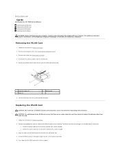
...card until it clicks in the connector slot. 4. Remove the computer cover (see Removing the Computer Cover). 3. Insert the WLAN card at www.dell.com/regulatory_compliance. Press down on the label (black and white): l Connect the black cable to the connector marked with a white triangle. 3....ensure correct insertion. l Connect the white cable to remove the antenna cables from under the card. Back to Contents Page Cards Dell Studio One 19/1909 Service Manual Removing the WLAN Card Replacing the WLAN Card Removing the RF Module Replacing the RF Module WARNING: Before working inside...
...card until it clicks in the connector slot. 4. Remove the computer cover (see Removing the Computer Cover). 3. Insert the WLAN card at www.dell.com/regulatory_compliance. Press down on the label (black and white): l Connect the black cable to the connector marked with a white triangle. 3....ensure correct insertion. l Connect the white cable to remove the antenna cables from under the card. Back to Contents Page Cards Dell Studio One 19/1909 Service Manual Removing the WLAN Card Replacing the WLAN Card Removing the RF Module Replacing the RF Module WARNING: Before working inside...
Service Manual
Page 5
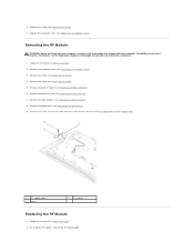
... the Right Speaker) 8. For additional safety best practices information, see Removing the Computer Cover). 3. Remove the computer cover (see the Regulatory Compliance Homepage at www.dell.com/regulatory_compliance. 1. Remove the optical drive (see Replacing the Shield). 7. To install the RF module, connect the RF module cable. Remove the screw securing the...
... the Right Speaker) 8. For additional safety best practices information, see Removing the Computer Cover). 3. Remove the computer cover (see the Regulatory Compliance Homepage at www.dell.com/regulatory_compliance. 1. Remove the optical drive (see Replacing the Shield). 7. To install the RF module, connect the RF module cable. Remove the screw securing the...
Service Manual
Page 6
Replace the computer cover (see Replacing the Optical Drive). 6. Replace the optical drive (see Replacing the Computer Cover). Replace the right speaker (see Replacing the Shield). 11. Replace the shield (see Replacing the Right Speaker). 7. Replace the processor fan (see Replacing the Stand). 10. 3. Replace the screw that secures the RF module. 5. Replace the stand (see Replacing the Processor Fan). 8. Back to Contents Page Replace the back I/O panel (see Replacing the Back I/O Panel). 9. Flip the RF module and align the screw hole on the RF module with the screw ...
Replace the computer cover (see Replacing the Optical Drive). 6. Replace the optical drive (see Replacing the Computer Cover). Replace the right speaker (see Replacing the Shield). 11. Replace the shield (see Replacing the Right Speaker). 7. Replace the processor fan (see Replacing the Stand). 10. 3. Replace the screw that secures the RF module. 5. Replace the stand (see Replacing the Processor Fan). 8. Back to Contents Page Replace the back I/O panel (see Replacing the Back I/O Panel). 9. Flip the RF module and align the screw hole on the RF module with the screw ...
Service Manual
Page 7
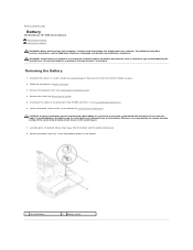
... dispose of its socket with a blunt object, be careful not to the connectors HDD_POWER and SATA_1 (see Removing the Shield). 5. Back to Contents Page Battery Dell Studio One 19/1909 Service Manual Removing the Battery Replacing the Battery WARNING: Before working inside your computer. CAUTION: If you can explode if it is inserted between...
... dispose of its socket with a blunt object, be careful not to the connectors HDD_POWER and SATA_1 (see Removing the Shield). 5. Back to Contents Page Battery Dell Studio One 19/1909 Service Manual Removing the Battery Replacing the Battery WARNING: Before working inside your computer. CAUTION: If you can explode if it is inserted between...

Service Manual
Page 8
Replace the computer cover (see Replacing the Shield). 5. Enter system setup (see System Board Components). 4. Follow the procedures in step 1. Replacing the Battery 1. Back to electrical outlets, and then turn them on. 7. Connect your computer and devices to Contents Page Replace the shield (see Replacing the Computer Cover). 6. Reconnect the cables to the connectors HDD_POWER and SATA_1 (see System Setup) and restore the settings you recorded in Before You Begin. 2. Insert the new battery into the socket with the side labeled "+" facing up and then snap the battery into...
Replace the computer cover (see Replacing the Shield). 5. Enter system setup (see System Board Components). 4. Follow the procedures in step 1. Replacing the Battery 1. Back to electrical outlets, and then turn them on. 7. Connect your computer and devices to Contents Page Replace the shield (see Replacing the Computer Cover). 6. Reconnect the cables to the connectors HDD_POWER and SATA_1 (see System Setup) and restore the settings you recorded in Before You Begin. 2. Insert the new battery into the socket with the side labeled "+" facing up and then snap the battery into...
Service Manual
Page 9
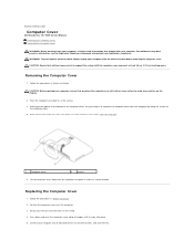
Back to Contents Page Computer Cover Dell Studio One 19/1909 Service Manual Removing the Computer Cover Replacing the Computer Cover WARNING: Before working inside your computer, read the safety information that shipped with the computer cover removed-at www.dell.com/regulatory_compliance. Removing the Computer Cover 1. Position the computer cover over the computer. 3. Place the...
Back to Contents Page Computer Cover Dell Studio One 19/1909 Service Manual Removing the Computer Cover Replacing the Computer Cover WARNING: Before working inside your computer, read the safety information that shipped with the computer cover removed-at www.dell.com/regulatory_compliance. Removing the Computer Cover 1. Position the computer cover over the computer. 3. Place the...

Service Manual
Page 11
...screws that shipped with your computer, read the safety information that secure the support assembly to Contents Page Support Assembly Dell Studio One 19/1909 Service Manual Removing the Support Assembly Replacing the Support Assembly WARNING: Before working inside your computer. Disconnect the ... pad connector l touch panel cable from the touch panel module Remove the inverter (see the Regulatory Compliance Homepage at www.dell.com/regulatory_compliance. Removing the Support Assembly 1. Remove the power supply unit (see Removing the System Board). 8. Remove the system...
...screws that shipped with your computer, read the safety information that secure the support assembly to Contents Page Support Assembly Dell Studio One 19/1909 Service Manual Removing the Support Assembly Replacing the Support Assembly WARNING: Before working inside your computer. Disconnect the ... pad connector l touch panel cable from the touch panel module Remove the inverter (see the Regulatory Compliance Homepage at www.dell.com/regulatory_compliance. Removing the Support Assembly 1. Remove the power supply unit (see Removing the System Board). 8. Remove the system...

Service Manual
Page 12
Replace the hard drive (see Replacing the Power Supply Unit). 6. Replace the power supply unit (see Replacing the Hard Drive). 5. Replace the side I/O panel (see Replacing the Inverter). 8. Replace the inverter (see Replacing the Side I/O Panel). 9. Back to the LCD panel: l LVDS cable from LVDS connector l touch pad cable from the touch pad connector l touch panel cable from the touch panel module 3. Reconnect the following cables to Contents Page Replace the system board (see Replacing the Optical Drive). 7. Follow the instructions in Before You Begin. 2. Replace the ...
Replace the hard drive (see Replacing the Power Supply Unit). 6. Replace the power supply unit (see Replacing the Hard Drive). 5. Replace the side I/O panel (see Replacing the Inverter). 8. Replace the inverter (see Replacing the Side I/O Panel). 9. Back to the LCD panel: l LVDS cable from LVDS connector l touch pad cable from the touch pad connector l touch panel cable from the touch panel module 3. Reconnect the following cables to Contents Page Replace the system board (see Replacing the Optical Drive). 7. Follow the instructions in Before You Begin. 2. Replace the ...
Service Manual
Page 13
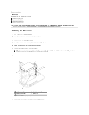
Follow the procedures in Before You Begin. 2. Slide the hard drive towards you are not replacing the hard drive at www.dell.com/regulatory_compliance. Disconnect the hard drive connector from the chassis. 6. Remove the shield (see Removing the Computer Cover). 3. NOTE:... data cable 4 grooves (2) 8. Back to the hard drive carrier. Remove the four screws securing the hard drive to Contents Page Drives Dell Studio One 19/1909 Service Manual Removing the Hard Drive Replacing the Hard Drive Removing the Optical Drive Replacing the Optical Drive WARNING: Before working inside your...
Follow the procedures in Before You Begin. 2. Slide the hard drive towards you are not replacing the hard drive at www.dell.com/regulatory_compliance. Disconnect the hard drive connector from the chassis. 6. Remove the shield (see Removing the Computer Cover). 3. NOTE:... data cable 4 grooves (2) 8. Back to the hard drive carrier. Remove the four screws securing the hard drive to Contents Page Drives Dell Studio One 19/1909 Service Manual Removing the Hard Drive Replacing the Hard Drive Removing the Optical Drive Replacing the Optical Drive WARNING: Before working inside your...
Service Manual
Page 14
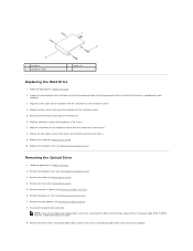
Prepare the new hard drive for your computer. 3. Align the screw holes on the hard drive carrier with the screw holes on the chassis. 8. Follow the procedures in the chassis. 7. Remove the back I/O panel (see Removing the Right Speaker). 8. Replace the four screws that secure the hard drive to verify that secures the hard drive carrier to the chassis and slide the optical drive carrier out of the data cable (SATA_2) and power cable (ODD_POWER) from the system board and set it aside. 9. Remove the right speaker (see Removing the Back I/O Panel). 6. NOTE: If you are not ...
Prepare the new hard drive for your computer. 3. Align the screw holes on the hard drive carrier with the screw holes on the chassis. 8. Follow the procedures in the chassis. 7. Remove the back I/O panel (see Removing the Right Speaker). 8. Replace the four screws that secure the hard drive to verify that secures the hard drive carrier to the chassis and slide the optical drive carrier out of the data cable (SATA_2) and power cable (ODD_POWER) from the system board and set it aside. 9. Remove the right speaker (see Removing the Back I/O Panel). 6. NOTE: If you are not ...
Service Manual
Page 15
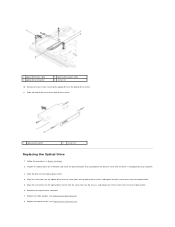
Follow the procedures in Before You Begin. 2. Align the screw holes on the optical drive carrier with the screw holes on the chassis, and replace the three screws that the drive is configured for your computer. 3. 1 optical drive data cable 3 optical drive connector 2 optical drive power cable 4 screws (3) 10. Prepare the optical drive for installation and check the documentation that accompanied the drive to the optical drive carrier. 11. Align the screw holes on the optical drive with the screw holes on the optical drive carrier, and replace the four screws that secure the ...
Follow the procedures in Before You Begin. 2. Align the screw holes on the optical drive carrier with the screw holes on the chassis, and replace the three screws that the drive is configured for your computer. 3. 1 optical drive data cable 3 optical drive connector 2 optical drive power cable 4 screws (3) 10. Prepare the optical drive for installation and check the documentation that accompanied the drive to the optical drive carrier. 11. Align the screw holes on the optical drive with the screw holes on the optical drive carrier, and replace the four screws that secure the ...

Service Manual
Page 16
Replace the shield (see Replacing the Computer Cover). Replace the computer cover (see Replacing the Shield). 12. Replace the back I /O Panel). 10. Back to Contents Page Replace the stand (see Replacing the Back I /O panel (see Replacing the Stand). 11. 9.
Replace the shield (see Replacing the Computer Cover). Replace the computer cover (see Replacing the Shield). 12. Replace the back I /O Panel). 10. Back to Contents Page Replace the stand (see Replacing the Back I /O panel (see Replacing the Stand). 11. 9.

Service Manual
Page 17
... additional safety best practices information, see Removing the Stand). 5. Follow the procedures in your system board. Back to Contents Page Processor Fan and Heat Sink Dell Studio One 19/1909 Service Manual Removing the Heat Sink Replacing the Heat Sink Removing the Processor Fan Replacing the Processor Fan WARNING: Before working inside your computer...
... additional safety best practices information, see Removing the Stand). 5. Follow the procedures in your system board. Back to Contents Page Processor Fan and Heat Sink Dell Studio One 19/1909 Service Manual Removing the Heat Sink Replacing the Heat Sink Removing the Processor Fan Replacing the Processor Fan WARNING: Before working inside your computer...

Service Manual
Page 18
Follow the procedures in Before You Begin. 2. Clean the thermal grease from the connector (CPU_FAN1) on the processor at the lower end of the processor heat sink. 5. Replace the back I/O panel (see Removing the Computer Cover). 3. Follow the procedures in Before You Begin. Remove the computer cover (see Replacing the Back I/O Panel). 7. Removing the Processor Fan WARNING: Do not touch the fan when the computer is achieved. 2. Remove the three screws securing the processor fan. 5. If either the processor or the processor heat sink is replaced, use the thermal grease ...
Follow the procedures in Before You Begin. 2. Clean the thermal grease from the connector (CPU_FAN1) on the processor at the lower end of the processor heat sink. 5. Replace the back I/O panel (see Removing the Computer Cover). 3. Follow the procedures in Before You Begin. Remove the computer cover (see Replacing the Back I/O Panel). 7. Removing the Processor Fan WARNING: Do not touch the fan when the computer is achieved. 2. Remove the three screws securing the processor fan. 5. If either the processor or the processor heat sink is replaced, use the thermal grease ...
Service Manual
Page 19
6. Follow the procedures in a secure location. Back to the connector (CPU_FAN1) on the system board. 3. Replace the shield (see Replacing the Computer Cover). Replace the three screws securing the processor fan. 4. Replacing the Processor Fan 1. Lift the processor fan away from the computer and place it in Before You Begin. 2. Connect the processor fan cable to Contents Page Replace the computer cover (see Replacing the Shield). 5.
6. Follow the procedures in a secure location. Back to the connector (CPU_FAN1) on the system board. 3. Replace the shield (see Replacing the Computer Cover). Replace the three screws securing the processor fan. 4. Replacing the Processor Fan 1. Lift the processor fan away from the computer and place it in Before You Begin. 2. Connect the processor fan cable to Contents Page Replace the computer cover (see Replacing the Shield). 5.

Service Manual
Page 20
...the chassis. 10. Lift the inverter out of the chassis. 1 screws (2) 3 inverter cable 2 cables to Contents Page Inverter Dell Studio One 19/1909 Service Manual Removing the Inverter Replacing the Inverter WARNING: Before working inside your computer, read the safety information that shipped with ... safety best practices information, see Removing the Computer Cover). 3. Remove the computer cover (see the Regulatory Compliance Homepage at www.dell.com/regulatory_compliance. Remove the shield (see Removing the Heat Sink and Removing the Processor Fan). 7. Remove the processor fan and heat...
...the chassis. 10. Lift the inverter out of the chassis. 1 screws (2) 3 inverter cable 2 cables to Contents Page Inverter Dell Studio One 19/1909 Service Manual Removing the Inverter Replacing the Inverter WARNING: Before working inside your computer, read the safety information that shipped with ... safety best practices information, see Removing the Computer Cover). 3. Remove the computer cover (see the Regulatory Compliance Homepage at www.dell.com/regulatory_compliance. Remove the shield (see Removing the Heat Sink and Removing the Processor Fan). 7. Remove the processor fan and heat...
Service Manual
Page 21
Replace the stand (see Replacing the Optical Drive). 6. Back to the chassis. 5. Replace the two screws that secure the inverter to Contents Page Replace the optical drive (see Replacing the Stand). 10. To replace the inverter, connect the two cables from the LCD panel to the system board connector (INVERTER). 4. Connect the inverter cable to the inverter. 3. Replace the right speaker (see Replacing the Shield). 11. Follow the procedures in Before You Begin. 2. Replace the shield (see Replacing the Right Speaker). 7. Replace the back I/O panel (see Replacing the ...
Replace the stand (see Replacing the Optical Drive). 6. Back to the chassis. 5. Replace the two screws that secure the inverter to Contents Page Replace the optical drive (see Replacing the Stand). 10. To replace the inverter, connect the two cables from the LCD panel to the system board connector (INVERTER). 4. Connect the inverter cable to the inverter. 3. Replace the right speaker (see Replacing the Shield). 11. Follow the procedures in Before You Begin. 2. Replace the shield (see Replacing the Right Speaker). 7. Replace the back I/O panel (see Replacing the ...
