
Microsoft Windows 7: Getting Started Guide
Page 1
...WLAN adapter is not a part of purchase. Microsoft Windows 7: Getting Started Guide Set Up Windows 7 Your Dell computer is preconfigured with the Microsoft® Windows® 7 operating system if you can purchase one at www.dell.com. The Windows setup screens will need an external modem or network connection and an Internet... it is recommended that you through several procedures including accepting license agreements, setting preferences, and setting up Windows for your computer available at support.dell.com. CAUTION: Do not interrupt the operating system's setup process.
...WLAN adapter is not a part of purchase. Microsoft Windows 7: Getting Started Guide Set Up Windows 7 Your Dell computer is preconfigured with the Microsoft® Windows® 7 operating system if you can purchase one at www.dell.com. The Windows setup screens will need an external modem or network connection and an Internet... it is recommended that you through several procedures including accepting license agreements, setting preferences, and setting up Windows for your computer available at support.dell.com. CAUTION: Do not interrupt the operating system's setup process.

Microsoft Windows 7: Getting Started Guide
Page 2
Setting Up Your Internet Connection ISPs and ISP offerings vary by country. Contact your ISP information ready. If you get one. Have your ISP to check the service status, or try connecting again later. To set up your connection to a wireless router: 1 Ensure that wireless is enabled on the screen to complete the setup. To set up your computer. 2 Save and close any open files, and exit any open programs. 2 3 Click Start → Control Panel→ Network and Sharing Center→ Connect to a network. 4 Follow the instructions on your Internet connection: 1 Save and close ...
Setting Up Your Internet Connection ISPs and ISP offerings vary by country. Contact your ISP information ready. If you get one. Have your ISP to check the service status, or try connecting again later. To set up your connection to a wireless router: 1 Ensure that wireless is enabled on the screen to complete the setup. To set up your computer. 2 Save and close any open files, and exit any open programs. 2 3 Click Start → Control Panel→ Network and Sharing Center→ Connect to a network. 4 Follow the instructions on your Internet connection: 1 Save and close ...

Microsoft Windows 7: Getting Started Guide
Page 3
...instructions on the screen and use the setup information provided by your ISP to complete the setup. Windows 7 Basic Features Customizing the Desktop You can customize your desktop to a new computer: 1 Click Start → Control Panel. 2 In the search box, type Transfer and then click Transfer...Set up files and folders on the Configure Backup wizard. 3 NOTE: If you periodically back up backup.... 3 Follow the instructions on your desktop: 1 Right-click an open the Change the visuals and sounds on your computer window and learn more about your customization options. To customize...
...instructions on the screen and use the setup information provided by your ISP to complete the setup. Windows 7 Basic Features Customizing the Desktop You can customize your desktop to a new computer: 1 Click Start → Control Panel. 2 In the search box, type Transfer and then click Transfer...Set up files and folders on the Configure Backup wizard. 3 NOTE: If you periodically back up backup.... 3 Follow the instructions on your desktop: 1 Right-click an open the Change the visuals and sounds on your computer window and learn more about your customization options. To customize...

Microsoft Windows 7: Getting Started Guide
Page 4
...the United States and/or other countries. is subject to change the boot sequence for one time only. Dell Inc. disclaims any manner whatsoever without notice. © 2009 Dell Inc. All rights reserved. After you reinstall the operating system, you must also reinstall the device drivers, ...any open files and exit any key to the devices specified in trademarks and trade names other software. NOTE: If you see the Microsoft Windows desktop; To reinstall Windows 7: 1 Save and close any open programs. 2 Insert the Operating System disc. 3 Click Exit if the Install Windows ...
...the United States and/or other countries. is subject to change the boot sequence for one time only. Dell Inc. disclaims any manner whatsoever without notice. © 2009 Dell Inc. All rights reserved. After you reinstall the operating system, you must also reinstall the device drivers, ...any open files and exit any key to the devices specified in trademarks and trade names other software. NOTE: If you see the Microsoft Windows desktop; To reinstall Windows 7: 1 Save and close any open programs. 2 Insert the Operating System disc. 3 Click Exit if the Install Windows ...

Service Manual
Page 1
...to either the entities claiming the marks and names or their products. Reproduction of Dell Inc.; Microsoft a n d Windows are trademarks of these materials in this text: Dell, the DELL logo, and Dell Studio are either potential damage to hardware or loss of data and tells you make... and trade names other countries. Trademarks used in any proprietary interest in the United States and/or other than its own. Dell Studio™ 540 Service Manual Technical Overview Before You Begin Replacing the Computer Cover Replacing the Front Panel Replacing Memory Module(s) Replacing ...
...to either the entities claiming the marks and names or their products. Reproduction of Dell Inc.; Microsoft a n d Windows are trademarks of these materials in this text: Dell, the DELL logo, and Dell Studio are either potential damage to hardware or loss of data and tells you make... and trade names other countries. Trademarks used in any proprietary interest in the United States and/or other than its own. Dell Studio™ 540 Service Manual Technical Overview Before You Begin Replacing the Computer Cover Replacing the Front Panel Replacing Memory Module(s) Replacing ...

Service Manual
Page 2
... the components in Turning Off Your Computer and Safety Instructions. l A component can be replaced or-if purchased separately-installed by Dell™ is flat and clean to prevent the computer cover from being scratched. 2. For additional safety best practices information, see... the cable from your computer and all attached devices are correctly oriented and aligned. Back to Contents Page Before You Begin Dell Studio™ 540 Service Manual Technical Specifications Recommended Tools Turning Off Your Computer Safety Instructions This chapter provides procedures for about 4 ...
... the components in Turning Off Your Computer and Safety Instructions. l A component can be replaced or-if purchased separately-installed by Dell™ is flat and clean to prevent the computer cover from being scratched. 2. For additional safety best practices information, see... the cable from your computer and all attached devices are correctly oriented and aligned. Back to Contents Page Before You Begin Dell Studio™ 540 Service Manual Technical Specifications Recommended Tools Turning Off Your Computer Safety Instructions This chapter provides procedures for about 4 ...

Service Manual
Page 3
While you work, periodically touch an unpainted metal surface to Contents Page NOTICE: Before touching anything inside your computer, ground yourself by touching an unpainted metal surface, such as the metal at the back of the computer. Back to dissipate static electricity, which could harm internal components.
While you work, periodically touch an unpainted metal surface to Contents Page NOTICE: Before touching anything inside your computer, ground yourself by touching an unpainted metal surface, such as the metal at the back of the computer. Back to dissipate static electricity, which could harm internal components.
Service Manual
Page 4
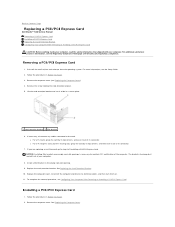
... corners, and ease it out of its connector. 7. Replace the computer cover, reconnect the computer and devices to Contents Page Replacing a PCI/PCI Express Card Dell Studio™ 540 Service Manual Removing a PCI/PCI Express Card Installing a PCI/PCI Express Card Replacing the Card Retention Bracket Configuring Your Computer After Removing or...
... corners, and ease it out of its connector. 7. Replace the computer cover, reconnect the computer and devices to Contents Page Replacing a PCI/PCI Express Card Dell Studio™ 540 Service Manual Removing a PCI/PCI Express Card Installing a PCI/PCI Express Card Replacing the Card Retention Bracket Configuring Your Computer After Removing or...

Service Manual
Page 5
Prepare the card for information about the card's cable connections. 11. See the documentation that the card is aligned with the card for information on configuring, customizing and making internal connections on . 12. See Replacing the Card Retention Bracket. Remove the screw holding the card retention bracket. 4. Replace the card retention bracket. Cables routed over or behind the cards. Remove the filler bracket to the equipment. 10. Ensure that came with the securing tab. 1 PCI Express x16 card 3 PCI Express x1 card 5 PCI Express x16 card slot 2 securing tab 4...
Prepare the card for information about the card's cable connections. 11. See the documentation that the card is aligned with the card for information on configuring, customizing and making internal connections on . 12. See Replacing the Card Retention Bracket. Remove the screw holding the card retention bracket. 4. Replace the card retention bracket. Cables routed over or behind the cards. Remove the filler bracket to the equipment. 10. Ensure that came with the securing tab. 1 PCI Express x16 card 3 PCI Express x1 card 5 PCI Express x16 card slot 2 securing tab 4...

Service Manual
Page 6
Enter system setup (see System Setup). 2. Removed 1. Go to Integrated Peripherals and select Onboard Audio Controller change the setting to Enabled. 3. Connect the network cable to Contents Page Go to Integrated Peripherals and select Onboard LAN Controller change the setting to Disabled. 3. l The notch in the top of the card or filler bracket fits around the alignment guide. 1 alignment guide 3 alignment bar 5 guide clamps (2) 2 filler bracket 4 card retention bracket 6 guide notchs (2) Configuring Your Computer After Removing or Installing a PCI/PCI Express Card NOTE: For ...
Enter system setup (see System Setup). 2. Removed 1. Go to Integrated Peripherals and select Onboard Audio Controller change the setting to Enabled. 3. Connect the network cable to Contents Page Go to Integrated Peripherals and select Onboard LAN Controller change the setting to Disabled. 3. l The notch in the top of the card or filler bracket fits around the alignment guide. 1 alignment guide 3 alignment bar 5 guide clamps (2) 2 filler bracket 4 card retention bracket 6 guide notchs (2) Configuring Your Computer After Removing or Installing a PCI/PCI Express Card NOTE: For ...

Service Manual
Page 7
... system and properly dispose of its socket with the object. Discard used batteries according to Contents Page Replacing the Battery Dell Studio™ 540 Service Manual CAUTION: Before working inside your computer, read the safety information that shipped with your computer... to the manufacturer's instructions. 1. Follow the procedures in step 1. Remove the computer cover (see the Regulatory Compliance Homepage at www.dell.com/regulatory_compliance. Enter system setup (see System Setup) so that the object is incorrectly installed. Record all the screens in system setup...
... system and properly dispose of its socket with the object. Discard used batteries according to Contents Page Replacing the Battery Dell Studio™ 540 Service Manual CAUTION: Before working inside your computer, read the safety information that shipped with your computer... to the manufacturer's instructions. 1. Follow the procedures in step 1. Remove the computer cover (see the Regulatory Compliance Homepage at www.dell.com/regulatory_compliance. Enter system setup (see System Setup) so that the object is incorrectly installed. Record all the screens in system setup...

Service Manual
Page 8
... 30 cm (1 ft.) of the computer lift it away from the electrical outlet before removing the cover. Back to Contents Page Replacing the Computer Cover Dell Studio™ 540 Service Manual CAUTION: Before working inside your computer, read the safety information that sufficient space exists to support the system with your computer...
... 30 cm (1 ft.) of the computer lift it away from the electrical outlet before removing the cover. Back to Contents Page Replacing the Computer Cover Dell Studio™ 540 Service Manual CAUTION: Before working inside your computer, read the safety information that sufficient space exists to support the system with your computer...

Service Manual
Page 9
...your system board. Lift up the processor to remove it from the tab that secures it. 6. Back to Contents Page Replacing the Processor Dell Studio™ 540 Service Manual CAUTION: Before working inside the socket or allow any objects to cool before you touch it aside in the ...new processor. Remove the processor fan and heat sink assembly from the ATX POWER and ATX_CPU connectors (see the Regulatory Compliance Homepage at www.dell.com/regulatory_compliance. NOTICE: Do not perform the following steps unless you replace the processor. 5. Be sure that it has had sufficient time ...
...your system board. Lift up the processor to remove it from the tab that secures it. 6. Back to Contents Page Replacing the Processor Dell Studio™ 540 Service Manual CAUTION: Before working inside the socket or allow any objects to cool before you touch it aside in the ...new processor. Remove the processor fan and heat sink assembly from the ATX POWER and ATX_CPU connectors (see the Regulatory Compliance Homepage at www.dell.com/regulatory_compliance. NOTICE: Do not perform the following steps unless you replace the processor. 5. Be sure that it has had sufficient time ...

Service Manual
Page 10
NOTICE: Socket pins are delicate. Be careful not to touch or bend the pins on the system board. 19. Align the pin-1 corners of the processor. 17. When the processor is a requirement for ensuring adequate thermal bonding, which is fully seated in the socket, close the processor cover. Clean the thermal grease from the ATX POWER and ATX_CPU connectors (see System Board Components) on the system board. 10. NOTICE: Ensure that the processor aligns properly with the socket, and do not use excessive force when you apply new thermal grease. Replace the computer cover (see Replacing ...
NOTICE: Socket pins are delicate. Be careful not to touch or bend the pins on the system board. 19. Align the pin-1 corners of the processor. 17. When the processor is a requirement for ensuring adequate thermal bonding, which is fully seated in the socket, close the processor cover. Clean the thermal grease from the ATX POWER and ATX_CPU connectors (see System Board Components) on the system board. 10. NOTICE: Ensure that the processor aligns properly with the socket, and do not use excessive force when you apply new thermal grease. Replace the computer cover (see Replacing ...

Service Manual
Page 12
.../regulatory_compliance. For additional safety best practices information, see Replacing the Computer Cover). 3. Back to Contents Page Replacing Drives Dell Studio™ 540 Service Manual Replacing a Hard Drive Replacing a CD/DVD Drive Replacing the FlexDock Removing the FlexDock Break-Away Metal Plate Replacing the FlexDock Drive ...
.../regulatory_compliance. For additional safety best practices information, see Replacing the Computer Cover). 3. Back to Contents Page Replacing Drives Dell Studio™ 540 Service Manual Replacing a Hard Drive Replacing a CD/DVD Drive Replacing the FlexDock Removing the FlexDock Break-Away Metal Plate Replacing the FlexDock Drive ...

Service Manual
Page 13
To replace the hard drive, check the documentation for your computer. 7. Connect the power and data cables to the CD/DVD drive. Replacing a CD/DVD Drive 1. Push and slide the CD/DVD drive out through the front of the CD/DVD drive. If you are not replacing the drive: a. Connect the power and data cables to the hard drive. 11. Align the four screw holes in the hard drive with the screw holes in the hard drive bay. 9. Replace the computer cover (see Replacing the Computer Cover). 3. Go to the chassis. 11. Slide the hard drive into place. 9. Remove the computer cover ...
To replace the hard drive, check the documentation for your computer. 7. Connect the power and data cables to the CD/DVD drive. Replacing a CD/DVD Drive 1. Push and slide the CD/DVD drive out through the front of the CD/DVD drive. If you are not replacing the drive: a. Connect the power and data cables to the hard drive. 11. Align the four screw holes in the hard drive with the screw holes in the hard drive bay. 9. Replace the computer cover (see Replacing the Computer Cover). 3. Go to the chassis. 11. Slide the hard drive into place. 9. Remove the computer cover ...

Service Manual
Page 14
Replace the front panel (see Replacing the Drive Panel Insert). Remove the drive panel insert, if applicable (see Replacing the Front Panel). 13. Gently slide the FlexDock into place in the FlexDock. 11. NOTE: Ensure that secure the FlexDock. NOTE: If you installed a new drive, see the documentation that came with the screw holes in the FlexDock slot. 10. Replacing the FlexDock 1. Disconnect the FlexDock USB cable from the back of the FlexDock and from its packaging. 9. If you are installing a new FlexDock: a. Connect the FlexDock USB cable to the back of the ...
Replace the front panel (see Replacing the Drive Panel Insert). Remove the drive panel insert, if applicable (see Replacing the Front Panel). 13. Gently slide the FlexDock into place in the FlexDock. 11. NOTE: Ensure that secure the FlexDock. NOTE: If you installed a new drive, see the documentation that came with the screw holes in the FlexDock slot. 10. Replacing the FlexDock 1. Disconnect the FlexDock USB cable from the back of the FlexDock and from its packaging. 9. If you are installing a new FlexDock: a. Connect the FlexDock USB cable to the back of the ...

Service Manual
Page 15
Removing the FlexDock Break-Away Metal Plate Align the tip of the FlexDock or CD/DVD drive and push the panel insert and push the panel insert until it is recommended that you replace the FlexDock drive insert whenever the FlexDock drive is removed from the front panel. 4. Remove the front panel (see Replacing the Computer Cover). 15. Gently press on the insert lever outward to break and remove the metal plate. Connect your computer and devices to electrical outlets, and then turn them on the break-away metal plate and rotate the screwdriver outwards to release the lock...
Removing the FlexDock Break-Away Metal Plate Align the tip of the FlexDock or CD/DVD drive and push the panel insert and push the panel insert until it is recommended that you replace the FlexDock drive insert whenever the FlexDock drive is removed from the front panel. 4. Remove the front panel (see Replacing the Computer Cover). 15. Gently press on the insert lever outward to break and remove the metal plate. Connect your computer and devices to electrical outlets, and then turn them on the break-away metal plate and rotate the screwdriver outwards to release the lock...

Service Manual
Page 16
Remove the front panel (see Replacing a PCI/PCI Express Card). An incorrectly routed or a disconnected cable could lead to the system board. Replace and tighten the screw that secures the Media Card Reader to the chassis. 7. Remove the screw that secures the Media Card Reader to the chassis. 10. Remove any expansion cards (see Replacing the Front Panel). 4. Reconnect the cables to computer problems. 5. Disconnect the cable that is removed from the computer. 1 back of each cable before you disconnect it is recommended that you are sure to re-route cables ...
Remove the front panel (see Replacing a PCI/PCI Express Card). An incorrectly routed or a disconnected cable could lead to the system board. Replace and tighten the screw that secures the Media Card Reader to the chassis. 7. Remove the screw that secures the Media Card Reader to the chassis. 10. Remove any expansion cards (see Replacing the Front Panel). 4. Reconnect the cables to computer problems. 5. Disconnect the cable that is removed from the computer. 1 back of each cable before you disconnect it is recommended that you are sure to re-route cables ...

Service Manual
Page 17
Replace any expansion cards (see Replacing the Front Panel). 13. Connect your computer and devices to Contents Page Replace the front panel (see Replacing a PCI/PCI Express Card). 12. 11. Back to an electrical outlet, and turn them on. Replace the computer cover (see Replacing the Computer Cover). 14.
Replace any expansion cards (see Replacing the Front Panel). 13. Connect your computer and devices to Contents Page Replace the front panel (see Replacing a PCI/PCI Express Card). 12. 11. Back to an electrical outlet, and turn them on. Replace the computer cover (see Replacing the Computer Cover). 14.
