
Owner's manual
Page 4
......29 Installing the System Board...31 System Board Components...32 3 System Setup...33 Boot Sequence...33 Navigation Keys...33 System Setup Options...34 Updating the BIOS ...40 Jumper Settings...40 System and Setup Password...41 Assigning a System Password and Setup Password 41 Deleting or Changing an Existing System and/or Setup... Pre-Boot System Assessment (ePSA) Diagnostics 43 5 Troubleshooting Your Computer 45 Power LED Diagnostics...45 Beep Code...46 Error Messages...46 6 Technical Specifications...49 7 Contacting Dell ...55
......29 Installing the System Board...31 System Board Components...32 3 System Setup...33 Boot Sequence...33 Navigation Keys...33 System Setup Options...34 Updating the BIOS ...40 Jumper Settings...40 System and Setup Password...41 Assigning a System Password and Setup Password 41 Deleting or Changing an Existing System and/or Setup... Pre-Boot System Assessment (ePSA) Diagnostics 43 5 Troubleshooting Your Computer 45 Power LED Diagnostics...45 Beep Code...46 Error Messages...46 6 Technical Specifications...49 7 Contacting Dell ...55

Owner's manual
Page 33
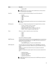
... drive number. • Optical Drive • Diagnostics NOTE: Choosing Diagnostics, will display the ePSA diagnostics screen. During the Power-on Self Test (POST), when the Dell logo appears, you can boot from including the diagnostic option. NOTE: For most of the system setup options, changes that you restart the system. Table...; View the system hardware configuration • Enable or disable integrated devices • Set performance and power management thresholds • Manage your computer hardware and specify BIOS‐level options.
... drive number. • Optical Drive • Diagnostics NOTE: Choosing Diagnostics, will display the ePSA diagnostics screen. During the Power-on Self Test (POST), when the Dell logo appears, you can boot from including the diagnostic option. NOTE: For most of the system setup options, changes that you restart the system. Table...; View the system hardware configuration • Enable or disable integrated devices • Set performance and power management thresholds • Manage your computer hardware and specify BIOS‐level options.
Owner's manual
Page 35
... disabled by default. This option is configured to enable or disable the various on the computer and its installed devices, the items listed in the BIOS setup irrespective of the SMART (Self Monitoring Analysis and Reporting Technology) specification. • Enable SMART Reporting - Allows you to define the serial port settings. Option...
... disabled by default. This option is configured to enable or disable the various on the computer and its installed devices, the items listed in the BIOS setup irrespective of the SMART (Self Monitoring Analysis and Reporting Technology) specification. • Enable SMART Reporting - Allows you to define the serial port settings. Option...

Owner's manual
Page 37
Changes to the Intel RAID (CTRL+I) or Intel Management Engine BIOS Extension (CTRL+P/F12). • Enable - Allows you to disabled. • Disable - User may enter OROM configuration screens via the hotkey. Allows you to enable or ... CPU XD Support - Option Password Change TPM Security Computrace(R) CPU XD Support OROM Keyboard Access Admin Setup Lockout Table 5. Allows you activate or disable the BIOS module interface of the processor. After the boot, the setting will improve with the additional cores. • All - This option is set to Enable by...
Changes to the Intel RAID (CTRL+I) or Intel Management Engine BIOS Extension (CTRL+P/F12). • Enable - Allows you to disabled. • Disable - User may enter OROM configuration screens via the hotkey. Allows you to enable or ... CPU XD Support - Option Password Change TPM Security Computrace(R) CPU XD Support OROM Keyboard Access Admin Setup Lockout Table 5. Allows you activate or disable the BIOS module interface of the processor. After the boot, the setting will improve with the additional cores. • All - This option is set to Enable by...

Owner's manual
Page 39
... Monitor (MVMM) can be enabled when the system boots. This option is not already set by default. Table 9. Allows you block entering to enter the BIOS Boot Option Menu. • Enable F12 Boot Option menu - This option is enabled by default. This option is not set . Option Block Sleep Description •...
... Monitor (MVMM) can be enabled when the system boots. This option is not already set by default. Table 9. Allows you block entering to enter the BIOS Boot Option Menu. • Enable F12 Boot Option menu - This option is enabled by default. This option is not set . Option Block Sleep Description •...

Owner's manual
Page 40
... a) Enter the Service Tag or Express Service Code and click Submit. The File Download window appears. 8. Click Run to update your BIOS (system setup), on replacing the system board or if an update is available on the bottom of the following table displays the jumper ...computer. Click Save to support.dell.com/support/downloads. 3. Table 11. Option SERR Messages Table 10. Select your preferred download method in the Please select your computer's service tag or express service code, select one of your computer. System Logs Option BIOS events Description Controls the SERR ...
... a) Enter the Service Tag or Express Service Code and click Submit. The File Download window appears. 8. Click Run to update your BIOS (system setup), on replacing the system board or if an update is available on the bottom of the following table displays the jumper ...computer. Click Save to support.dell.com/support/downloads. 3. Table 11. Option SERR Messages Table 10. Select your preferred download method in the Please select your computer's service tag or express service code, select one of your computer. System Logs Option BIOS events Description Controls the SERR ...
Owner's manual
Page 41
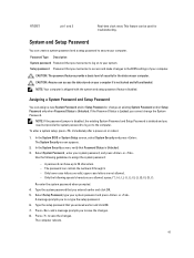
...setup, press immediately after a power-on your computer. In the System Security screen, verify that you must enter to log on to the BIOS settings of security for troubleshooting. A password can be used for the data on to save the changes. 8. Type the system password that... Password , enter your system password and press or . If the Password Status is Locked, you entered earlier and click OK. 5. In the System BIOS or System Setup screen, select System Security and press . The computer reboots. 41 RTCRST pin 1 and 2 Real-time clock reset. Assigning a System...
...setup, press immediately after a power-on your computer. In the System Security screen, verify that you must enter to log on to the BIOS settings of security for troubleshooting. A password can be used for the data on to save the changes. 8. Type the system password that... Password , enter your system password and press or . If the Password Status is Locked, you entered earlier and click OK. 5. In the System BIOS or System Setup screen, select System Security and press . The computer reboots. 41 RTCRST pin 1 and 2 Real-time clock reset. Assigning a System...
Owner's manual
Page 42
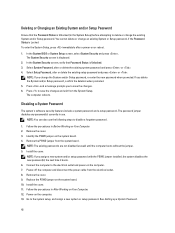
... existing passwords are not disabled (erased) until the computer boots without the jumper. 5. Remove the cover. 9. See Setting up a System Password. 42 In the System BIOS or System Setup screen, select System Security and press . If you assign a new system and/or setup password with the PSWD jumper installed, the system...
... existing passwords are not disabled (erased) until the computer boots without the jumper. 5. Remove the cover. 9. See Setting up a System Password. 42 In the System BIOS or System Setup screen, select System Security and press . If you assign a new system and/or setup password with the PSWD jumper installed, the system...
Owner's manual
Page 43
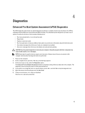
... you wish to test only your hardware. 4 Diagnostics Enhanced Pre-Boot System Assessment (ePSA) Diagnostics The ePSA diagnostics (also known as the Dell logo appears. 3. The embedded system diagnostics provides a set of your computer. On the boot menu screen, select the Diagnostics option. The ...results or error messages. The Enhanced Pre-boot System Assessment window is launched by the BIOS internally. If there are any issues, error codes are performed. 1. Note the error code and contact Dell. 43 As the computer boots, press the key as system diagnostics) performs a complete...
... you wish to test only your hardware. 4 Diagnostics Enhanced Pre-Boot System Assessment (ePSA) Diagnostics The ePSA diagnostics (also known as the Dell logo appears. 3. The embedded system diagnostics provides a set of your computer. On the boot menu screen, select the Diagnostics option. The ...results or error messages. The Enhanced Pre-boot System Assessment window is launched by the BIOS internally. If there are any issues, error codes are performed. 1. Note the error code and contact Dell. 43 As the computer boots, press the key as system diagnostics) performs a complete...
Owner's manual
Page 45
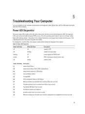
... LED State Description 2,1 system board failure 2,2 system board failure, PSU or PSU cabling failure 2,3 system board, memory or CPU failure 2, 4 Coin-cell battery failure 2,5 Corrupt BIOS 2,6 CPU configuration failure or CPU failure 2,7 Memory modules are detected, but a memory failure has occurred 3,1 Possible peripheral card or system board failure has occurred 3,2 A possible...
... LED State Description 2,1 system board failure 2,2 system board failure, PSU or PSU cabling failure 2,3 system board, memory or CPU failure 2, 4 Coin-cell battery failure 2,5 Corrupt BIOS 2,6 CPU configuration failure or CPU failure 2,7 Memory modules are detected, but a memory failure has occurred 3,1 Possible peripheral card or system board failure has occurred 3,2 A possible...

Owner's manual
Page 46
...Management features are disabled until it is removed. Code Cause 1-3-2 Memory failure Error Messages Error Message Description Address mark not found The BIOS found a faulty disk sector or could not find a particular disk sector. Alert! Data error The floppy or hard drive cannot read... or the associated controller is installed. Bad command or file name Ensure that you have failed at booting this checkpoint and contact Dell Technical Support. Diskette drive 0 seek failure A cable may be loose or the computer configuration information may be faulty or improperly ...
...Management features are disabled until it is removed. Code Cause 1-3-2 Memory failure Error Messages Error Message Description Address mark not found The BIOS found a faulty disk sector or could not find a particular disk sector. Alert! Data error The floppy or hard drive cannot read... or the associated controller is installed. Bad command or file name Ensure that you have failed at booting this checkpoint and contact Dell Technical Support. Diskette drive 0 seek failure A cable may be loose or the computer configuration information may be faulty or improperly ...

Owner's manual
Page 50
... PCIe x4. Network Feature Integrated Table 18. Expansion Bus Feature Bus Type Bus Speed: Table 20. System Information Feature System Chipset DMA Channels Interrupt Levels BIOS Chip (NVRAM) Table 19. Table 16.
... PCIe x4. Network Feature Integrated Table 18. Expansion Bus Feature Bus Type Bus Speed: Table 20. System Information Feature System Chipset DMA Channels Interrupt Levels BIOS Chip (NVRAM) Table 19. Table 16.


