Quick Reference Guide
Page 21
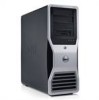
front fan card fan 5.25-inch drive bay with 3.5-inch drive panel plate 5.25-inch drive bay Quick Reference Guide 21 Inside View 1 2 7 6 1 2 3 4 5 6 7 3 5 4 power supply hard drive bay memory shroud NOTICE: The memory shroud holds the (optional) memory riser cards in order to secure the risers and to avoid damage. its thumbscrews must be sufficiently tight in place;
front fan card fan 5.25-inch drive bay with 3.5-inch drive panel plate 5.25-inch drive bay Quick Reference Guide 21 Inside View 1 2 7 6 1 2 3 4 5 6 7 3 5 4 power supply hard drive bay memory shroud NOTICE: The memory shroud holds the (optional) memory riser cards in order to secure the risers and to avoid damage. its thumbscrews must be sufficiently tight in place;

Quick Reference Guide
Page 23
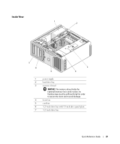
... connectors (SATA_0, SATA_1, SATA_2) 11 RTC reset jumper (RTCRST) 12 main power connector (POWER1) 13 hard drive connector (HDD_3) 14 hard drive connector (HDD_2) 15 hard drive connector (HDD_1) 16 hard drive connector (HDD_0) 17 hard drive fan (FAN_HDD) 18 FlexBay connector (USB) 19 floppy drive (DSKT) 20 front panel connector (FRONTPANEL) 21 front panel 1394 connector (FP1394) 22 chassis intrusion header...
... connectors (SATA_0, SATA_1, SATA_2) 11 RTC reset jumper (RTCRST) 12 main power connector (POWER1) 13 hard drive connector (HDD_3) 14 hard drive connector (HDD_2) 15 hard drive connector (HDD_1) 16 hard drive connector (HDD_0) 17 hard drive fan (FAN_HDD) 18 FlexBay connector (USB) 19 floppy drive (DSKT) 20 front panel connector (FRONTPANEL) 21 front panel 1394 connector (FP1394) 22 chassis intrusion header...
User Guide
Page 5
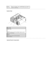
13 serial connector Connect a serial device, such as a handheld device, to avoid damage. 4 front fan 5 card fan 6 5.25-inch drive bay with 3.5-inch drive panel plate 7 5.25-inch drive bay System Board Components If necessary, the address for this port can be sufficiently tight in place; Inside View 1 power supply 2 hard drive bay 3 memory shroud NOTICE: The memory shroud holds the (optional) memory riser cards in order to secure the risers and to the serial port. its thumbscrews must be modified through system setup (see System Setup).
13 serial connector Connect a serial device, such as a handheld device, to avoid damage. 4 front fan 5 card fan 6 5.25-inch drive bay with 3.5-inch drive panel plate 7 5.25-inch drive bay System Board Components If necessary, the address for this port can be sufficiently tight in place; Inside View 1 power supply 2 hard drive bay 3 memory shroud NOTICE: The memory shroud holds the (optional) memory riser cards in order to secure the risers and to the serial port. its thumbscrews must be modified through system setup (see System Setup).

User Guide
Page 6
...This slot is not available in the dualgraphics configuration 28 PCI-Express x8 card slot, wired as x4 (SLOT7_PCIE) 8 auxiliary hard-drive LED connector (AUX_LED) 25 PCI-X card slot (SLOT6_PCIX) 9 air temperature sensor connector 26 PCI-X card slot (SLOT5_PCIX) 10... is replaced by a x16 slot on the graphics riser. 1 secondary processor 18 hard drive fan (FAN_HDD) connector (CPU_1) 2 front fan connector (FAN_FRONT) 19 FlexBay connector (USB) 3 card cage fan connector (FAN_CCAG) 20 floppy drive (DSKT) 4 internal speaker 21 front panel connector (FRONTPANEL) connector (INT_SPKR) 5...
...This slot is not available in the dualgraphics configuration 28 PCI-Express x8 card slot, wired as x4 (SLOT7_PCIE) 8 auxiliary hard-drive LED connector (AUX_LED) 25 PCI-X card slot (SLOT6_PCIX) 9 air temperature sensor connector 26 PCI-X card slot (SLOT5_PCIX) 10... is replaced by a x16 slot on the graphics riser. 1 secondary processor 18 hard drive fan (FAN_HDD) connector (CPU_1) 2 front fan connector (FAN_FRONT) 19 FlexBay connector (USB) 3 card cage fan connector (FAN_CCAG) 20 floppy drive (DSKT) 4 internal speaker 21 front panel connector (FRONTPANEL) connector (INT_SPKR) 5...

User Guide
Page 7
...fan connector (FAN_MEM) 32 white memory module connectors (DIMM_14) support memory modules or memory module risers 33 black memory module connectors (DIMM_5-8) support memory modules only when no memory riser cards are installed; 13 main power connector 30 (POWEsR1) NOTE: PCI-Express x8 card slot, wired as x4 (SLOT1_PCIE) 14 hard drive... connector (HDD_3) 15 hard drive connector (HDD_2) 16 hard drive connector (HDD_1) 17 hard drive connector (HDD_0) NOTE: In the dual-graphics configuration, this slot is replaced by...
...fan connector (FAN_MEM) 32 white memory module connectors (DIMM_14) support memory modules or memory module risers 33 black memory module connectors (DIMM_5-8) support memory modules only when no memory riser cards are installed; 13 main power connector 30 (POWEsR1) NOTE: PCI-Express x8 card slot, wired as x4 (SLOT1_PCIE) 14 hard drive... connector (HDD_3) 15 hard drive connector (HDD_2) 16 hard drive connector (HDD_1) 17 hard drive connector (HDD_0) NOTE: In the dual-graphics configuration, this slot is replaced by...
User Guide
Page 8
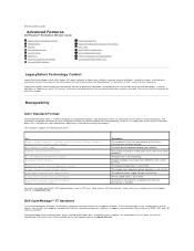
...hard-drive images, and help desk procedures. ASF is invalid (alert occurs after three failed attempts). The system password is designed to supersede previous operating system-absent alerting technologies. The computer temperature is out of limits. Dell OpenManage Client instrumentation, which are deactivated make resources available. Back to Contents Page Advanced Features Dell Precision...™ Workstation 690...Generic Critical Fan Failure ...
...hard-drive images, and help desk procedures. ASF is invalid (alert occurs after three failed attempts). The system password is designed to supersede previous operating system-absent alerting technologies. The computer temperature is out of limits. Dell OpenManage Client instrumentation, which are deactivated make resources available. Back to Contents Page Advanced Features Dell Precision...™ Workstation 690...Generic Critical Fan Failure ...
User Guide
Page 119
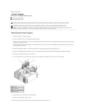
...Dell Precision™ Workstation 690 User's Guide Removing the Power Supply Replacing the Power Supply CAUTION: Before performing any of your computer's electronic components. NOTICE: To prevent static damage to prevent them from the electrical outlet before you touch any full-length expansion or graphics riser cards (see Removing a Hard Drive (Hard Drive..., discharge static electricity from the computer. 1 screws (4) 2 hard-drive bay 3 hard-drive fan release latch 4 hard-drive fan 8. Disconnect the hard drive fan from the chassis. 10. Remove the four screws that attach each...
...Dell Precision™ Workstation 690 User's Guide Removing the Power Supply Replacing the Power Supply CAUTION: Before performing any of your computer's electronic components. NOTICE: To prevent static damage to prevent them from the electrical outlet before you touch any full-length expansion or graphics riser cards (see Removing a Hard Drive (Hard Drive..., discharge static electricity from the computer. 1 screws (4) 2 hard-drive bay 3 hard-drive fan release latch 4 hard-drive fan 8. Disconnect the hard drive fan from the chassis. 10. Remove the four screws that attach each...
User Guide
Page 139
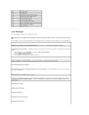
... follow the safety instructions in resolving this problem, please note this does not resolve the problem, contact Dell. (See "Contacting Dell" on page 259.) Alert! Alert! Front Fan Failure - 4-2-2 4-2-3 4-2-4 4-3-1 4-3-3 4-3-4 4-4-1 4-4-2 4-4-3 4-4-4 Shutdown failure Gate A20 failure Unexpected ...to the support technician. (See Contacting Dell.) Alert! Ensure that was not found - System thermal solution compromised. Replace system cover and reboot - NOTE: Single processor configurations must use these checks. Hard Drive Fan Failure - Alert! Chipset heatsink not...
... follow the safety instructions in resolving this problem, please note this does not resolve the problem, contact Dell. (See "Contacting Dell" on page 259.) Alert! Alert! Front Fan Failure - 4-2-2 4-2-3 4-2-4 4-3-1 4-3-3 4-3-4 4-4-1 4-4-2 4-4-3 4-4-4 Shutdown failure Gate A20 failure Unexpected ...to the support technician. (See Contacting Dell.) Alert! Ensure that was not found - System thermal solution compromised. Replace system cover and reboot - NOTE: Single processor configurations must use these checks. Hard Drive Fan Failure - Alert! Chipset heatsink not...
User Guide
Page 151
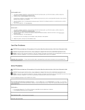
... to eliminate the possibility that the card fan cable is connected firmly to the card fan connector on the computer. Remove all cards. See Dell Diagnostics. See Dell Diagnostics. Card Fan Problems CAUTION: Before you just reinstalled is connected to a drive controller card and not to components inside ...NOTICE: To prevent static damage to check for and remove viruses. CAUTION: To guard against electrical shock, always unplug your primary hard drive is faulty and needs to electrical outlets, and then turn them on the computer. See Cleaning Your Computer. You can do...
... to eliminate the possibility that the card fan cable is connected firmly to the card fan connector on the computer. Remove all cards. See Dell Diagnostics. See Dell Diagnostics. Card Fan Problems CAUTION: Before you just reinstalled is connected to a drive controller card and not to components inside ...NOTICE: To prevent static damage to check for and remove viruses. CAUTION: To guard against electrical shock, always unplug your primary hard drive is faulty and needs to electrical outlets, and then turn them on the computer. See Cleaning Your Computer. You can do...


