
Service Manual
Page 5
... Microprocessor 107 Installation Guidelines 107 Upgrading the Microprocessor(s 107 Microprocessor Cooling Fan 113 Removing the Microprocessor Cooling Fan 113 Replacing the Microprocessor Cooling Fan 114 VRM 115 Removing a VRM 115 Installing a VRM 116 Computer Battery 119 System Board 123 Removing the System Board 123 Replacing the System Board 124 5
... Microprocessor 107 Installation Guidelines 107 Upgrading the Microprocessor(s 107 Microprocessor Cooling Fan 113 Removing the Microprocessor Cooling Fan 113 Replacing the Microprocessor Cooling Fan 114 VRM 115 Removing a VRM 115 Installing a VRM 116 Computer Battery 119 System Board 123 Removing the System Board 123 Replacing the System Board 124 5
Service Manual
Page 24
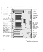
....dell.com | support.dell.com RIMM sockets (4) CD audio input connector system board speaker System Board Components VRM 0 connector microprocessor 0 with heat sink microprocessor 0 fan connector parallel and serial (2) port connectors microprocessor 1 fan connector PS/2 keyboard and mouse connectors audio connectors IEEE 1394 connector microprocessor 1 with heat sink network and Port 1 USB (2) connectors VRM...
....dell.com | support.dell.com RIMM sockets (4) CD audio input connector system board speaker System Board Components VRM 0 connector microprocessor 0 with heat sink microprocessor 0 fan connector parallel and serial (2) port connectors microprocessor 1 fan connector PS/2 keyboard and mouse connectors audio connectors IEEE 1394 connector microprocessor 1 with heat sink network and Port 1 USB (2) connectors VRM...

Service Manual
Page 26
... standby power light on the system board. Otherwise, damage to -RAM light Telephony connector Network and Port 2 USB (2) connectors VRM 0 connector VRM 1 connector Jumpers The following figure shows the location of the jumpers on the system board has turned off its pin(s) and carefully... fit it down onto the pin(s) indicated. 26 To locate this light, see "System Board Components." www.dell.com | support.dell.com S y s t e m B o a r d L a b e l s...
... standby power light on the system board. Otherwise, damage to -RAM light Telephony connector Network and Port 2 USB (2) connectors VRM 0 connector VRM 1 connector Jumpers The following figure shows the location of the jumpers on the system board has turned off its pin(s) and carefully... fit it down onto the pin(s) indicated. 26 To locate this light, see "System Board Components." www.dell.com | support.dell.com S y s t e m B o a r d L a b e l s...
Service Manual
Page 107
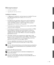
..."System Board Components." • For single-processor operations, the processor must be installed in socket 0 and the VRM must be installed in connector 0. NOTICE: Dell recommends that only a technically knowledgeable person perform this procedure. If the processors do not match, the diagnostic lights ... each microprocessor installed. Then install the VRM(s) from the upgrade kit. If the VRMs do not match, you touch it. 107 Upgrading the Microprocessor(s) NOTE: Dell recommends that you use only microprocessors purchased from Dell, reuse the original VRM(s). • If you are not ...
..."System Board Components." • For single-processor operations, the processor must be installed in socket 0 and the VRM must be installed in connector 0. NOTICE: Dell recommends that only a technically knowledgeable person perform this procedure. If the processors do not match, the diagnostic lights ... each microprocessor installed. Then install the VRM(s) from the upgrade kit. If the VRMs do not match, you touch it. 107 Upgrading the Microprocessor(s) NOTE: Dell recommends that you use only microprocessors purchased from Dell, reuse the original VRM(s). • If you are not ...

Service Manual
Page 115
... after disconnecting the computer from the system board, verify that the standby power light on its electrical outlet. VRM • Removing a VRM • Installing a VRM NOTICE: A VRM must be installed for each end of the socket outward simultaneously until the module pops out slightly from the ... the following figure). 4 Lift the module away from the socket. 115 To locate this procedure, see "System Board Components." To locate the VRM and microprocessor sockets, see "Safety First- For You and Your Computer." Before removing a component from its right side, and open the computer...
... after disconnecting the computer from the system board, verify that the standby power light on its electrical outlet. VRM • Removing a VRM • Installing a VRM NOTICE: A VRM must be installed for each end of the socket outward simultaneously until the module pops out slightly from the ... the following figure). 4 Lift the module away from the socket. 115 To locate this procedure, see "System Board Components." To locate the VRM and microprocessor sockets, see "Safety First- For You and Your Computer." Before removing a component from its right side, and open the computer...

Service Manual
Page 116
... on the number of microprocessors installed. 1 Press the securing clips at each end of the socket outward until they snap open (see "Removing a VRM"). 2 Align the slots on the bottom of the module with the ridges inside the socket. 3 Press the module straight down into the socket until... the securing clips snap into place at the ends of its connector. www.dell.com | support.dell.com Removing a VRM VRM securing clip VRM connector 5 Grasp the VRM by its top corners, and ease it out of the module. 4 Install the airflow shroud. 5 Close the computer ...
... on the number of microprocessors installed. 1 Press the securing clips at each end of the socket outward until they snap open (see "Removing a VRM"). 2 Align the slots on the bottom of the module with the ridges inside the socket. 3 Press the module straight down into the socket until... the securing clips snap into place at the ends of its connector. www.dell.com | support.dell.com Removing a VRM VRM securing clip VRM connector 5 Grasp the VRM by its top corners, and ease it out of the module. 4 Install the airflow shroud. 5 Close the computer ...

Microprocessor Replacement
Page 8
... be installed for either single or dual processors, remove and discard the original VRM(s). If you are not installing a processor upgrade kit from Dell, reuse the original VRM(s). • If installing a Dell processor upgrade kit for each microprocessor installed. com 4 Verify that the standby power...and securing clips. If you are not installing a processor upgrade kit from Dell, reuse the original heat sink(s) and securing clips. 6 Microprocessor Replacement w w w.d el l.co m | su p po rt. If the VRMs do not match, you may not start. If the processors do not ...
... be installed for either single or dual processors, remove and discard the original VRM(s). If you are not installing a processor upgrade kit from Dell, reuse the original VRM(s). • If installing a Dell processor upgrade kit for each microprocessor installed. com 4 Verify that the standby power...and securing clips. If you are not installing a processor upgrade kit from Dell, reuse the original heat sink(s) and securing clips. 6 Microprocessor Replacement w w w.d el l.co m | su p po rt. If the VRMs do not match, you may not start. If the processors do not ...
Setup and Quick Reference Guide
Page 34
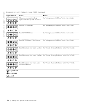
... Memory Problems" in the User's Guide. See "Microprocessor Problems" in the User's Guide. A B C D Possible VRM 0 and VRM 1 failure. A B C D Possible memory riser board B failure. www.dell.com | support.dell.com D i a g n o s t i c L i g h t C o d e s B e f o r e P O S T (continued) Light Pattern Cause Microprocessor and/or voltage regulator module (VRM) mismatch. A B C D Possible VRM 1 failure. A B C D Possible memory riser board A failure. See "Microprocessor Problems" in the User's Guide...
... Memory Problems" in the User's Guide. See "Microprocessor Problems" in the User's Guide. A B C D Possible VRM 0 and VRM 1 failure. A B C D Possible memory riser board B failure. www.dell.com | support.dell.com D i a g n o s t i c L i g h t C o d e s B e f o r e P O S T (continued) Light Pattern Cause Microprocessor and/or voltage regulator module (VRM) mismatch. A B C D Possible VRM 1 failure. A B C D Possible memory riser board A failure. See "Microprocessor Problems" in the User's Guide...


