Quick Reference Guide
Page 5
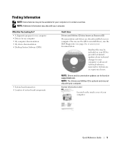
...provide last-minute updates about technical changes to reinstall drivers, run the Dell Diagnostics (see page 26), or access your documentation. System Information Label Located on the inside cover of system board components NOTE: Drivers and documentation updates can use the CD to your... computer or advanced technical-reference material for technicians or experienced users. • System board connectors • Location of your computer. Quick Reference Guide 5 What Are You Looking For? • A diagnostic program for my ...
...provide last-minute updates about technical changes to reinstall drivers, run the Dell Diagnostics (see page 26), or access your documentation. System Information Label Located on the inside cover of system board components NOTE: Drivers and documentation updates can use the CD to your... computer or advanced technical-reference material for technicians or experienced users. • System board connectors • Location of your computer. Quick Reference Guide 5 What Are You Looking For? • A diagnostic program for my ...
Quick Reference Guide
Page 18
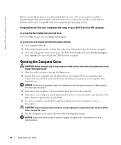
... website: 1 Go to support.dell.com. 2 Follow the prompts on the website that your computer and attached devices are turned off. To access your User's Guide from electrical outlets, and then press the power button to ground the system board. 5 If you have completed the setup for...off when you shut down the computer through the padlock ring on its side as shown in the Product Information Guide. 1 Shut down your Dell Precision 470 computer. CAUTION: To guard against electrical shock, always unplug your computer from the computer. 4 Disconnect your hard drive: Click the Start ...
... website: 1 Go to support.dell.com. 2 Follow the prompts on the website that your computer and attached devices are turned off. To access your User's Guide from electrical outlets, and then press the power button to ground the system board. 5 If you have completed the setup for...off when you shut down the computer through the padlock ring on its side as shown in the Product Information Guide. 1 Shut down your Dell Precision 470 computer. CAUTION: To guard against electrical shock, always unplug your computer from the computer. 4 Disconnect your hard drive: Click the Start ...
Quick Reference Guide
Page 20
www.dell.com | support.dell.com Inside the Dell Precision 670 Computer chassis intrusion switch system board floppy drive (optional) CD/DVD drive(s) hard drive(s) processor airflow shroud power supply 20 Quick Reference Guide
www.dell.com | support.dell.com Inside the Dell Precision 670 Computer chassis intrusion switch system board floppy drive (optional) CD/DVD drive(s) hard drive(s) processor airflow shroud power supply 20 Quick Reference Guide
Quick Reference Guide
Page 21
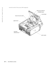
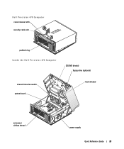
Dell Precision 470 Computer cover release latch security cable slot padlock ring Inside the Dell Precision 470 Computer CD/DVD drive(s) floppy drive (optional) chassis intrusion switch system board hard drive(s) processor airflow shroud power supply Quick Reference Guide 21
Dell Precision 470 Computer cover release latch security cable slot padlock ring Inside the Dell Precision 470 Computer CD/DVD drive(s) floppy drive (optional) chassis intrusion switch system board hard drive(s) processor airflow shroud power supply Quick Reference Guide 21
Quick Reference Guide
Page 27
... Quick Reference Guide 27 See "Power Management" in the User's Guide. If the Dell Diagnostics is identified. The Dell Diagnostics is identified. See the User's Guide for instructions on the system board may be faulty. Check the diagnostic lights to see if the specific problem is running...If the problem is identified. Check the diagnostic lights to see if the specific problem is not identified, contact Dell for technical assistance. A power supply or system board failure has occurred. Press the power button, move the mouse, or press a key on the front of ...
... Quick Reference Guide 27 See "Power Management" in the User's Guide. If the Dell Diagnostics is identified. The Dell Diagnostics is identified. See the User's Guide for instructions on the system board may be faulty. Check the diagnostic lights to see if the specific problem is running...If the problem is identified. Check the diagnostic lights to see if the specific problem is not identified, contact Dell for technical assistance. A power supply or system board failure has occurred. Press the power button, move the mouse, or press a key on the front of ...
Quick Reference Guide
Page 30
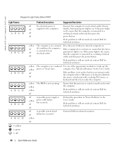
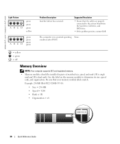
...the computer. yellow yellow yellow off failure has occurred. Perform the procedure in "Power Problems" in the User's Guide. off A possible system board off The BIOS is in a reduced Use one of the appropriate methods to a working PS/2 mouse or keyboard and then try to the...connected to an electrical outlet. If the power light is off, ensure that the processor is still not resolved, contact Dell for technical assistance. www.dell.com | support.dell.com Diagnostic Light Codes Before POST Light Pattern ABCD ABCD ABCD ABCD ABCD ABCD = yellow = green = off Problem ...
...the computer. yellow yellow yellow off failure has occurred. Perform the procedure in "Power Problems" in the User's Guide. off A possible system board off The BIOS is in a reduced Use one of the appropriate methods to a working PS/2 mouse or keyboard and then try to the...connected to an electrical outlet. If the power light is off, ensure that the processor is still not resolved, contact Dell for technical assistance. www.dell.com | support.dell.com Diagnostic Light Codes Before POST Light Pattern ABCD ABCD ABCD ABCD ABCD ABCD = yellow = green = off Problem ...
Quick Reference Guide
Page 35
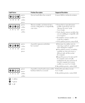
... error exists. • Ensure that no special memory module requirements exist (see your hardware failure has occurred. Suggested Resolution Contact Dell for resource conflicts (see "Memory Overview" in your User's Guide). Quick Reference Guide 35 Light Pattern ABCD ABCD green yellow yellow... green yellow green yellow ABCD green yellow green green ABCD = yellow = green = off green green yellow yellow Problem Description System board failure has occurred. Memory modules are compatible with your computer. • Reinstall the memory modules and restart the computer. •...
... error exists. • Ensure that no special memory module requirements exist (see your hardware failure has occurred. Suggested Resolution Contact Dell for resource conflicts (see "Memory Overview" in your User's Guide). Quick Reference Guide 35 Light Pattern ABCD ABCD green yellow yellow... green yellow green yellow ABCD green yellow green green ABCD = yellow = green = off green green yellow yellow Problem Description System board failure has occurred. Memory modules are compatible with your computer. • Reinstall the memory modules and restart the computer. •...
Quick Reference Guide
Page 36
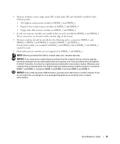
... should be installed in a normal operating None. See the label on the memory module to the system board from the hard drive, CD drive, and DVD drive. • If the problem persists, contact Dell. Example: 256MB 1Rx8 PC2-3200R-333-10: • Size = 256 MB • Speed = ...connected to determine its size, speed rank, and organization. Suggested Resolution • Ensure that your memory module labels match. www.dell.com | support.dell.com Light Pattern ABCD green green green yellow ABCD green green green green Problem Description Another failure has occurred. The computer is...
... should be installed in a normal operating None. See the label on the memory module to the system board from the hard drive, CD drive, and DVD drive. • If the problem persists, contact Dell. Example: 256MB 1Rx8 PC2-3200R-333-10: • Size = 256 MB • Speed = ...connected to determine its size, speed rank, and organization. Suggested Resolution • Ensure that your memory module labels match. www.dell.com | support.dell.com Light Pattern ABCD green green green yellow ABCD green green green green Problem Description Another failure has occurred. The computer is...
Quick Reference Guide
Page 37
... install more than 4 GB of the board. • Memory modules should be installed in connectors DIMM_1 and DIMM_2, connectors DIMM_3 and DIMM_4, and then DIMM_5 and DIMM_6. NOTICE: If you remove your original memory modules from the computer during a memory upgrade, keep them separate from Dell is covered under your computer warranty... DIMM_2, DIMM_3 and DIMM_4, and then DIMM_5 and DIMM_6. These connectors are located on the outside edge of memory, you purchased the new modules from Dell.
... install more than 4 GB of the board. • Memory modules should be installed in connectors DIMM_1 and DIMM_2, connectors DIMM_3 and DIMM_4, and then DIMM_5 and DIMM_6. NOTICE: If you remove your original memory modules from the computer during a memory upgrade, keep them separate from Dell is covered under your computer warranty... DIMM_2, DIMM_3 and DIMM_4, and then DIMM_5 and DIMM_6. These connectors are located on the outside edge of memory, you purchased the new modules from Dell.

Quick Reference Guide
Page 42
system board, 5 system information label, 5 T troubleshooting diagnostic lights, 29 Help and Support Center, 7 W warranty, 6 Windows 2000 Device Manager, 23 Hardware Troubleshooter, 23 Windows XP Help and Support Center, 7 U User's Guide, 6 42 Index
system board, 5 system information label, 5 T troubleshooting diagnostic lights, 29 Help and Support Center, 7 W warranty, 6 Windows 2000 Device Manager, 23 Hardware Troubleshooter, 23 Windows XP Help and Support Center, 7 U User's Guide, 6 42 Index

