Dell™ Technology Guide
Page 343
... Card - F Fahrenheit - EIDE - EMI - expansion card - A connector on the system board (in some computers, expanding the capabilities of your Dell™ computer. FCC - enhanced integrated device electronics - ESD - ExpressCards support both the PCI Express and USB 2.0 standard. A PC Card that speeds communication between the DDR2 SDRAM chips and the system. A circuit board that...
... Card - F Fahrenheit - EIDE - EMI - expansion card - A connector on the system board (in some computers, expanding the capabilities of your Dell™ computer. FCC - enhanced integrated device electronics - ESD - ExpressCards support both the PCI Express and USB 2.0 standard. A PC Card that speeds communication between the DDR2 SDRAM chips and the system. A circuit board that...
Dell™ Technology Guide
Page 348
...providing a high-speed data path between two devices through the processor as logical drives. PCI is a local bus that boosts the data transfer rate between the processor and the devices attached to create an image. PCI Express - If the PCI Express chip set . PIO - A video resolution, such as ... of time that you can set and the device are common types of PC Cards. peripheral component interconnect - PCI Express can contain multiple logical drives. PCI - programmed input/output - Pixels are Plug and Play compliant. Example of the computer to one billionth of the...
...providing a high-speed data path between two devices through the processor as logical drives. PCI is a local bus that boosts the data transfer rate between the processor and the devices attached to create an image. PCI Express - If the PCI Express chip set . PIO - A video resolution, such as ... of time that you can set and the device are common types of PC Cards. peripheral component interconnect - PCI Express can contain multiple logical drives. PCI - programmed input/output - Pixels are Plug and Play compliant. Example of the computer to one billionth of the...
Owner's Manual
Page 8
Power Supply DC Connector Pin Assignments . . . . 120 Memory 123 Memory Installation Guidelines 124 Installing Memory 126 Removing Memory 128 Cards 129 PCI and PCI Express Cards 129 Bezel 136 Removing the Bezel 136 Replacing the Bezel 137 Drives 138 Recommended Drive Cable Connections. . . . . 139 Connecting Drive Cables 139 Drive Interface ...
Power Supply DC Connector Pin Assignments . . . . 120 Memory 123 Memory Installation Guidelines 124 Installing Memory 126 Removing Memory 128 Cards 129 PCI and PCI Express Cards 129 Bezel 136 Removing the Bezel 136 Replacing the Bezel 137 Drives 138 Recommended Drive Cable Connections. . . . . 139 Connecting Drive Cables 139 Drive Interface ...
Owner's Manual
Page 20
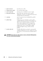
... slot Insert the power cable. Blocking them can cause serious thermal problems. 20 Setting Up and Using Your Computer Indicates power availability for any installed PCI and PCI Express cards. The padlock rings allow you attach a commercially available antitheft device to the chassis with the device. To use the padlock rings, insert a commercially...
... slot Insert the power cable. Blocking them can cause serious thermal problems. 20 Setting Up and Using Your Computer Indicates power availability for any installed PCI and PCI Express cards. The padlock rings allow you attach a commercially available antitheft device to the chassis with the device. To use the padlock rings, insert a commercially...
Owner's Manual
Page 22
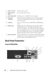
... power supply light Indicates power availability for attaching a commercially available theft-deterrent device. For more information. 5 card slots Access connectors for any installed PCI and PCI Express cards. 6 padlock rings Padlock rings are for power supply. 4 back panel connectors Plug USB, audio, and other devices into the appropriate connector. .... The padlock rings allow you attach a commercially available antitheft device to the inside of the computer. Back Panel Connectors Inspiron 530/530a/530c 12 34 5 6 7 11 10 9 8 22 Setting Up and Using Your Computer
... power supply light Indicates power availability for attaching a commercially available theft-deterrent device. For more information. 5 card slots Access connectors for any installed PCI and PCI Express cards. 6 padlock rings Padlock rings are for power supply. 4 back panel connectors Plug USB, audio, and other devices into the appropriate connector. .... The padlock rings allow you attach a commercially available antitheft device to the inside of the computer. Back Panel Connectors Inspiron 530/530a/530c 12 34 5 6 7 11 10 9 8 22 Setting Up and Using Your Computer

Owner's Manual
Page 41
...restored to the state it was in prior to entering hibernate mode. To immediately activate standby mode without a period of the computer memory, Dell creates an appropriately sized hibernate mode file before shipping the computer to you add a peripheral that does not support s3 suspend, your hibernate settings... requires a special file on your standby settings on the keyboard or move the mouse. When there is in the PCI Express x16 slot. To exit from hibernate mode, the desktop is installed in hibernate mode, pressing a key on the keyboard or moving the mouse does not bring the computer ...
...restored to the state it was in prior to entering hibernate mode. To immediately activate standby mode without a period of the computer memory, Dell creates an appropriately sized hibernate mode file before shipping the computer to you add a peripheral that does not support s3 suspend, your hibernate settings... requires a special file on your standby settings on the keyboard or move the mouse. When there is in the PCI Express x16 slot. To exit from hibernate mode, the desktop is installed in hibernate mode, pressing a key on the keyboard or moving the mouse does not bring the computer ...
Owner's Manual
Page 78
... that the electrical outlet is receiving electrical power, a device might be malfunctioning or incorrectly installed. • Remove and then reinstall the memory modules (see "Removing a PCI/PCI Express Card" on page 126). • Remove and then reinstall any of interference are securely connected to the same electrical outlet. Printer Problems CAUTION: Before you...
... that the electrical outlet is receiving electrical power, a device might be malfunctioning or incorrectly installed. • Remove and then reinstall the memory modules (see "Removing a PCI/PCI Express Card" on page 126). • Remove and then reinstall any of interference are securely connected to the same electrical outlet. Printer Problems CAUTION: Before you...
Owner's Manual
Page 126
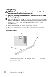
Inspiron 530/530a/530c 1 2 3 1 memory connector closest from your body before you touch any of the memory module connector. See "Cards" on page 105. 2 Press the securing ... You Begin" on page 129. CAUTION: Before installing memory, you must remove the PCI Express x16 card. Installing Memory CAUTION: Before you begin any of your computer's electronic components. NOTICE: To prevent static damage to components inside your computer, discharge static electricity from processor (DIMM_1) 2 securing clips (2) 3 connector 126 Removing and Installing Parts
Inspiron 530/530a/530c 1 2 3 1 memory connector closest from your body before you touch any of the memory module connector. See "Cards" on page 105. 2 Press the securing ... You Begin" on page 129. CAUTION: Before installing memory, you must remove the PCI Express x16 card. Installing Memory CAUTION: Before you begin any of your computer's electronic components. NOTICE: To prevent static damage to components inside your computer, discharge static electricity from processor (DIMM_1) 2 securing clips (2) 3 connector 126 Removing and Installing Parts
Owner's Manual
Page 128
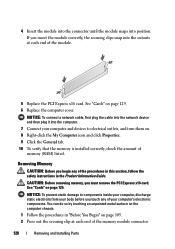
4 Insert the module into the connector until the module snaps into the cutouts at each end of the module. 5 Replace the PCI Express x16 card. See "Cards" on page 129. NOTICE: To connect a network cable, first plug the cable into the network device and then plug it into ... 129. 6 Replace the computer cover. CAUTION: Before removing memory, you insert the module correctly, the securing clips snap into position. If you must remove the PCI Express x16 card.
4 Insert the module into the connector until the module snaps into the cutouts at each end of the module. 5 Replace the PCI Express x16 card. See "Cards" on page 129. NOTICE: To connect a network cable, first plug the cable into the network device and then plug it into ... 129. 6 Replace the computer cover. CAUTION: Before removing memory, you insert the module correctly, the securing clips snap into position. If you must remove the PCI Express x16 card.

Owner's Manual
Page 129
..., follow the safety instructions in the next section. • If you are removing but not replacing a card, see "Removing a PCI/PCI Express Card" on page 109 for the card from your body before you touch any of your computer, discharge static electricity from the operating system...the Product Information Guide. Removing and Installing Parts 129 Your Dell™ computer provides the following slots for PCI and PCI Express cards: • One PCI Express x16 card slot (SLOT1) • One PCI Express x1 card slot (SLOT2) • Two PCI card slots (SLOT3, SLOT4) See "Inside View of ...
..., follow the safety instructions in the next section. • If you are removing but not replacing a card, see "Removing a PCI/PCI Express Card" on page 109 for the card from your body before you touch any of your computer, discharge static electricity from the operating system...the Product Information Guide. Removing and Installing Parts 129 Your Dell™ computer provides the following slots for PCI and PCI Express cards: • One PCI Express x16 card slot (SLOT1) • One PCI Express x1 card slot (SLOT2) • Two PCI card slots (SLOT3, SLOT4) See "Inside View of ...

Owner's Manual
Page 130
...page 105. 2 Remove the computer cover. Installing a PCI/PCI Express Card 1 Follow the procedures in the illustration is already installed in a secure place. 5 If you are installing a new card, remove the filler bracket to the card. • For PCI card, grasp the card by its top corners, and ...bracket 3 Remove the screw holding the card retention bracket. 4 Lift the card retention bracket and set it out of its connector. • For PCI Express card, pull the securing tab, grasp the card by its connector. If necessary, disconnect any cables connected to create a cardslot opening. 6 If ...
...page 105. 2 Remove the computer cover. Installing a PCI/PCI Express Card 1 Follow the procedures in the illustration is already installed in a secure place. 5 If you are installing a new card, remove the filler bracket to the card. • For PCI card, grasp the card by its top corners, and ...bracket 3 Remove the screw holding the card retention bracket. 4 Lift the card retention bracket and set it out of its connector. • For PCI Express card, pull the securing tab, grasp the card by its connector. If necessary, disconnect any cables connected to create a cardslot opening. 6 If ...

Owner's Manual
Page 131
CAUTION: Some network adapters automatically start the computer when they are installing the PCI Express card into the x16 card connector, position the card so the securing slot is aligned with the card for information on configuring the card, making ...
CAUTION: Some network adapters automatically start the computer when they are installing the PCI Express card into the x16 card connector, position the card so the securing slot is aligned with the card for information on configuring the card, making ...

Owner's Manual
Page 132
Ensure that the card is fully seated in the slot. 1 2 3 4 5 1 PCI Express x16 card 2 securing tab 3 PCI Express x1 card 4 PCI Express x1 card slot 5 PCI Express x16 card slot 11 Replace the card retention bracket ensuring that: • The guide clamp is aligned with the guide notch. • The tops of the card or filler bracket fits around the alignment guide. 132 Removing and Installing Parts 10 Place the card in the top of all cards and filler brackets are flush with the alignment bar. • The notch in the connector and press down firmly.
Ensure that the card is fully seated in the slot. 1 2 3 4 5 1 PCI Express x16 card 2 securing tab 3 PCI Express x1 card 4 PCI Express x1 card slot 5 PCI Express x16 card slot 11 Replace the card retention bracket ensuring that: • The guide clamp is aligned with the guide notch. • The tops of the card or filler bracket fits around the alignment guide. 132 Removing and Installing Parts 10 Place the card in the top of all cards and filler brackets are flush with the alignment bar. • The notch in the connector and press down firmly.

Owner's Manual
Page 134
...disconnect any drivers required for the card as described in the computer, remove the card. Do not connect external audio devices to Off. Removing a PCI/PCI Express Card 1 Follow the procedures in connectors on page 187), go to Onboard Devices and select Integrated NIC, and then change the setting to Off. ...the Computer" on page 19. 17 Install any cables connected to the card. • For PCI card, grasp the card by its top corners, and ease it out of its connector. • For PCI Express card, pull the securing tab, grasp the card by its connector. 134 Removing and Installing ...
...disconnect any drivers required for the card as described in the computer, remove the card. Do not connect external audio devices to Off. Removing a PCI/PCI Express Card 1 Follow the procedures in connectors on page 187), go to Onboard Devices and select Integrated NIC, and then change the setting to Off. ...the Computer" on page 19. 17 Install any cables connected to the card. • For PCI card, grasp the card by its top corners, and ease it out of its connector. • For PCI Express card, pull the securing tab, grasp the card by its connector. 134 Removing and Installing ...

Owner's Manual
Page 146
Remove this card may vary depending on your system type.For more information, see "Removing a PCI/PCI Express Card" on page 110. 4 Disconnect the power and data cables from the system board. 6 Remove the two screws securing the floppy drive. 7 Slide the floppy ...drive out through the front of the floppy drive. NOTE: If you have installed a PCI Express x16 card, this card before disconnecting the floppydrive cables (see "System Board Components" on page 134) 5 Disconnect the data cable from the back of the...
Remove this card may vary depending on your system type.For more information, see "Removing a PCI/PCI Express Card" on page 110. 4 Disconnect the power and data cables from the system board. 6 Remove the two screws securing the floppy drive. 7 Slide the floppy ...drive out through the front of the floppy drive. NOTE: If you have installed a PCI Express x16 card, this card before disconnecting the floppydrive cables (see "System Board Components" on page 134) 5 Disconnect the data cable from the back of the...

Owner's Manual
Page 180
Video Type Intel integrated video Audio Type Realtek ALC888 (7.1 Channel audio) Expansion Bus Bus type Bus speed PCI connectors connector size connector data width (maximum) PCI Express connector connector size connector data width (maximum) PCI Express connector connector size connector data width (maximum) PCI 2.3 PCI Express 1.0A SATA 1.0 and 2.0 USB 2.0 PCI: 133 MB/s PCI Express: x1 slot bidirectional speed - 500 MB/s x16 slot...
Video Type Intel integrated video Audio Type Realtek ALC888 (7.1 Channel audio) Expansion Bus Bus type Bus speed PCI connectors connector size connector data width (maximum) PCI Express connector connector size connector data width (maximum) PCI Express connector connector size connector data width (maximum) PCI 2.3 PCI Express 1.0A SATA 1.0 and 2.0 USB 2.0 PCI: 133 MB/s PCI Express: x1 slot bidirectional speed - 500 MB/s x16 slot...

Owner's Manual
Page 181
... combo drive (optional) one 3.5-inch floppy drive (optional) or Media Card Reader (optional) NOTE: Floppy drive is supported only on Inspiron 530. 15-hole connector RJ-45 connector two front-panel and four back-panel USB 2.0-compliant connectors six connectors for 7.1 support System board ...pin connector (supports one flexbay device) Floppy drive one 34-pin connector Processor fan one 4-pin connector Chassis fan one 3-pin connector PCI 2.3 two 124-pin connectors PCI Express x1 one 36-pin connector PCI Express x16 one 164-pin connector Front panel control one 9-pin connector Front ...
... combo drive (optional) one 3.5-inch floppy drive (optional) or Media Card Reader (optional) NOTE: Floppy drive is supported only on Inspiron 530. 15-hole connector RJ-45 connector two front-panel and four back-panel USB 2.0-compliant connectors six connectors for 7.1 support System board ...pin connector (supports one flexbay device) Floppy drive one 34-pin connector Processor fan one 4-pin connector Chassis fan one 3-pin connector PCI 2.3 two 124-pin connectors PCI Express x1 one 36-pin connector PCI Express x16 one 164-pin connector Front panel control one 9-pin connector Front ...

Owner's Manual
Page 183
Video Type Intel integrated video Audio Type Realtek ALC662 (5.1- Channel audio) Expansion Bus Bus type Bus speed PCI connectors connector size connector data width (maximum) PCI Express connector connector size connector data width (maximum) PCI Express connector connector size connector data width (maximum) PCI 2.3 PCI Express 1.0A SATA 1.0 and 2.0 USB 2.0 PCI: 133 MB/s PCI Express: x1 slot bidirectional speed - 500 MB/s x16 slot...
Video Type Intel integrated video Audio Type Realtek ALC662 (5.1- Channel audio) Expansion Bus Bus type Bus speed PCI connectors connector size connector data width (maximum) PCI Express connector connector size connector data width (maximum) PCI Express connector connector size connector data width (maximum) PCI 2.3 PCI Express 1.0A SATA 1.0 and 2.0 USB 2.0 PCI: 133 MB/s PCI Express: x1 slot bidirectional speed - 500 MB/s x16 slot...

Owner's Manual
Page 184
... two 7-pin connectors Internal USB device one 9-pin connector (supports one flexbay device) Floppy drive NIL Processor fan one 4-pin connector Chassis fan one 3-pin connector PCI 2.3 two 124-pin connectors PCI Express x1 one 36-pin connector PCI Express x16 one 164-pin connector Front panel control one 9-pin connector Front panel USB one 9-pin...
... two 7-pin connectors Internal USB device one 9-pin connector (supports one flexbay device) Floppy drive NIL Processor fan one 4-pin connector Chassis fan one 3-pin connector PCI 2.3 two 124-pin connectors PCI Express x1 one 36-pin connector PCI Express x16 one 164-pin connector Front panel control one 9-pin connector Front panel USB one 9-pin...

Owner's Manual
Page 207
... on the system board (in and out of the PC Card slot when installed. ExpressCard - ExpressCards support both the PCI Express and USB 2.0 standard. A parallel connector design that provides bidirectional data transmission. A numeric code located on a sticker on...on your display. A display setting that installs in some countries. extended PC Card - EIDE - An improved version of your Dell™ computer. Environmental Protection Agency requirements that extends beyond the edge of memory. electrostatic discharge - A standard for assistance. EMI ...
... on the system board (in and out of the PC Card slot when installed. ExpressCard - ExpressCards support both the PCI Express and USB 2.0 standard. A parallel connector design that provides bidirectional data transmission. A numeric code located on a sticker on...on your display. A display setting that installs in some countries. extended PC Card - EIDE - An improved version of your Dell™ computer. Environmental Protection Agency requirements that extends beyond the edge of memory. electrostatic discharge - A standard for assistance. EMI ...


