
Inspiron-3656 Specifications
Page 2
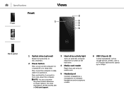
... in Power Options. Press to put the computer in sleep state if it is turned on. NOTE: You can customize the power‑button behaviour in sleep state. Specifications Front Front Back Views 2 1 3 4 5 6 Back panel 1 Optical drive (optional) Reads from and writes to 5 Gbps. Provides data transfer speeds up to media cards. 5 Headset port Connect a headphone, a microphone, or a headset (headphone and microphone combo). 6 USB 3.0 ports (2) Connect peripherals such as storage devices...
... in Power Options. Press to put the computer in sleep state if it is turned on. NOTE: You can customize the power‑button behaviour in sleep state. Specifications Front Front Back Views 2 1 3 4 5 6 Back panel 1 Optical drive (optional) Reads from and writes to 5 Gbps. Provides data transfer speeds up to media cards. 5 Headset port Connect a headphone, a microphone, or a headset (headphone and microphone combo). 6 USB 3.0 ports (2) Connect peripherals such as storage devices...

Inspiron-3656 Specifications
Page 3
... Back panel 2 3 7 4 6 5 1 Back panel Connect USB, audio, video, and other devices. 2 Expansion-card slots Provide access to ports on . While the computer is turned off and you press the power-supply diagnostic button, this light turns on if the power-supply unit is receiving power. 5 Power-supply diagnostic button While the computer is turned off, press this button to diagnose the power-supply unit. 6 Padlock rings Attach a padlock to prevent unauthorized access to the interior of your computer. 7 Security-cable slot Connect a security cable...
... Back panel 2 3 7 4 6 5 1 Back panel Connect USB, audio, video, and other devices. 2 Expansion-card slots Provide access to ports on . While the computer is turned off and you press the power-supply diagnostic button, this light turns on if the power-supply unit is receiving power. 5 Power-supply diagnostic button While the computer is turned off, press this button to diagnose the power-supply unit. 6 Padlock rings Attach a padlock to prevent unauthorized access to the interior of your computer. 7 Security-cable slot Connect a security cable...

Inspiron-3656 Specifications
Page 4
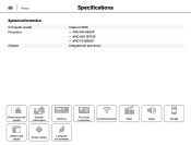
...the connector indicate the connectivity status and network activity. Specifications Back panel Front Back Views 21 3 4 5 6 7 Back panel 1 Line-in enabled device. The two lights next to 480 Mbps. 7 Network port Connect an Ethernet (RJ45) cable from a router or a broadband modem for network or internet access. Provides video and audio output. 6 USB 2.0 ports (4) Connect peripherals such as a microphone or CD player. 2 Line-out port Connect speakers. 3 Microphone port Connect an external microphone to provide sound input. 4 VGA port Connect an external display or a projector. 5 HDMI port...
...the connector indicate the connectivity status and network activity. Specifications Back panel Front Back Views 21 3 4 5 6 7 Back panel 1 Line-in enabled device. The two lights next to 480 Mbps. 7 Network port Connect an Ethernet (RJ45) cable from a router or a broadband modem for network or internet access. Provides video and audio output. 6 USB 2.0 ports (4) Connect peripherals such as a microphone or CD player. 2 Line-out port Connect speakers. 3 Microphone port Connect an external microphone to provide sound input. 4 VGA port Connect an external display or a projector. 5 HDMI port...
Inspiron-3656 Specifications
Page 6
Views System information Computer model Processor Chipset Specifications Inspiron 3656 • AMD A8-8600P • AMD A10-8700P • AMD FX-8800P Integrated in processor Dimensions and weight System information Memory Ports and connectors Communications Video Media-card reader Power ratings Computer environment Audio Storage
Views System information Computer model Processor Chipset Specifications Inspiron 3656 • AMD A8-8600P • AMD A10-8700P • AMD FX-8800P Integrated in processor Dimensions and weight System information Memory Ports and connectors Communications Video Media-card reader Power ratings Computer environment Audio Storage

Inspiron-3656 Specifications
Page 7
Views Memory Slot Type Speed Configurations supported Specifications Two DIMM slots DDR3L 1600 MHz 2 GB (Ubuntu only), 4 GB, 6 GB, 8 GB, 12 GB, and 16 GB Dimensions and weight System information Memory Ports and connectors Communications Video Media-card reader Power ratings Computer environment Audio Storage
Views Memory Slot Type Speed Configurations supported Specifications Two DIMM slots DDR3L 1600 MHz 2 GB (Ubuntu only), 4 GB, 6 GB, 8 GB, 12 GB, and 16 GB Dimensions and weight System information Memory Ports and connectors Communications Video Media-card reader Power ratings Computer environment Audio Storage

Inspiron-3656 Specifications
Page 8
... USB 2.0 ports • Two USB 3.0 ports • One headset port • One microphone port • One line-in port • One line-out port • One VGA port • One HDMI port One M.2 card slot for Wi-Fi and Bluetooth combo card • One PCIe x1 half-length full-height slot • One PCIe x16 full-length full-height slot Dimensions and weight System information Memory Ports and connectors Communications Video Media-card reader Power...
... USB 2.0 ports • Two USB 3.0 ports • One headset port • One microphone port • One line-in port • One line-out port • One VGA port • One HDMI port One M.2 card slot for Wi-Fi and Bluetooth combo card • One PCIe x1 half-length full-height slot • One PCIe x16 full-length full-height slot Dimensions and weight System information Memory Ports and connectors Communications Video Media-card reader Power...

Inspiron-3656 Specifications
Page 12
Views Storage Interface Configurations supported Specifications • SATA 3 Gbps for optical drive • SATA 6 Gbps for hard drive • One optical drive and one 3.5-inch hard drive • One optical drive and one 2.5-inch hard drive • One 3.5-inch hard drive and one 2.5-inch hard drive • Two 2.5-inch hard drives Dimensions and weight System information Memory Ports and connectors Communications Video Media-card reader Power ratings Computer environment Audio Storage
Views Storage Interface Configurations supported Specifications • SATA 3 Gbps for optical drive • SATA 6 Gbps for hard drive • One optical drive and one 3.5-inch hard drive • One optical drive and one 2.5-inch hard drive • One 3.5-inch hard drive and one 2.5-inch hard drive • Two 2.5-inch hard drives Dimensions and weight System information Memory Ports and connectors Communications Video Media-card reader Power ratings Computer environment Audio Storage

Inspiron-3656 Service Manual
Page 3
Contents Before working inside your computer 8 Before you begin 8 Safety instructions 8 Recommended tools 9 After working inside your computer 11 Technical overview 12 System board components 12 Removing the computer cover 14 Procedure...14 Replacing the computer cover 15 Procedure...15 Removing the front bezel 16 Prerequisites...16 Procedure...16 Replacing the front bezel 18 Procedure...18 Post-requisites 18 Removing the memory modules 19 Prerequisites...19 Procedure...20 Replacing the memory modules 22 Procedure...22 Post-requisites 23 3
Contents Before working inside your computer 8 Before you begin 8 Safety instructions 8 Recommended tools 9 After working inside your computer 11 Technical overview 12 System board components 12 Removing the computer cover 14 Procedure...14 Replacing the computer cover 15 Procedure...15 Removing the front bezel 16 Prerequisites...16 Procedure...16 Replacing the front bezel 18 Procedure...18 Post-requisites 18 Removing the memory modules 19 Prerequisites...19 Procedure...20 Replacing the memory modules 22 Procedure...22 Post-requisites 23 3

Inspiron-3656 Service Manual
Page 6
Removing the chassis fan 62 Prerequisites...62 Procedure...63 Replacing the chassis fan 66 Procedure...66 Post-requisites 66 Removing the front-panel light board 67 Prerequisites...67 Procedure...68 Replacing the front-panel light board 71 Procedure...71 Post-requisites 71 Removing the power-supply unit 72 Prerequisites...72 Procedure...73 Replacing the power-supply unit 76 Procedure...76 Postrequisites 76 Removing the processor fan 77 Prerequisites...77 Procedure...78 Replacing the processor fan 80 Procedure...80 Post-requisites 80 6
Removing the chassis fan 62 Prerequisites...62 Procedure...63 Replacing the chassis fan 66 Procedure...66 Post-requisites 66 Removing the front-panel light board 67 Prerequisites...67 Procedure...68 Replacing the front-panel light board 71 Procedure...71 Post-requisites 71 Removing the power-supply unit 72 Prerequisites...72 Procedure...73 Replacing the power-supply unit 76 Procedure...76 Postrequisites 76 Removing the processor fan 77 Prerequisites...77 Procedure...78 Replacing the processor fan 80 Procedure...80 Post-requisites 80 6

Inspiron-3656 Service Manual
Page 8
... system board. NOTE: The images in this document may differ from your computer depending on , from your computer. 6 Remove any media card and optical disc from your computer, if applicable. 7 After the computer is unplugged, press and hold the power button for shut-down instructions. 3 Disconnect your computer and all open applications. 2 Shut down your computer. - Before you ordered. Before working inside your...
... system board. NOTE: The images in this document may differ from your computer depending on , from your computer. 6 Remove any media card and optical disc from your computer, if applicable. 7 After the computer is unplugged, press and hold the power button for shut-down instructions. 3 Disconnect your computer and all open applications. 2 Shut down your computer. - Before you ordered. Before working inside your...
Inspiron-3656 Service Manual
Page 9
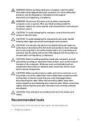
... on the cable itself. When connecting cables, ensure that shipped with your computer. WARNING: Before working inside the computer, replace all power sources before opening the computer cover or panels. For more safety best practices, see the Regulatory Compliance home page at the back of the computer. CAUTION: You should only perform troubleshooting and repairs as the metal at www.dell.com/regulatory_compliance...
... on the cable itself. When connecting cables, ensure that shipped with your computer. WARNING: Before working inside the computer, replace all power sources before opening the computer cover or panels. For more safety best practices, see the Regulatory Compliance home page at the back of the computer. CAUTION: You should only perform troubleshooting and repairs as the metal at www.dell.com/regulatory_compliance...

Inspiron-3656 Service Manual
Page 11
After working inside your computer CAUTION: Leaving stray or loose screws inside your computer may severely damage your computer. 1 Replace all screws and ensure that no stray screws remain inside your computer. 2 Connect any external devices, peripherals, and cables you removed before working on your computer. 3 Replace any media cards, discs, and any other parts that you removed before working on your computer. 4 Connect your computer and all attached devices to their electrical outlets. 5 Turn on your computer. 11
After working inside your computer CAUTION: Leaving stray or loose screws inside your computer may severely damage your computer. 1 Replace all screws and ensure that no stray screws remain inside your computer. 2 Connect any external devices, peripherals, and cables you removed before working on your computer. 3 Replace any media cards, discs, and any other parts that you removed before working on your computer. 4 Connect your computer and all attached devices to their electrical outlets. 5 Turn on your computer. 11

Inspiron-3656 Service Manual
Page 12
... shipped with your computer and follow the instructions in Before working inside your computer. For more safety best practices, see the Regulatory Compliance home page at www.dell.com/regulatory_compliance. System board components 1 chassis-fan cable connector 2 memory-module slots (2) 3 coin-cell battery 4 power-button cable connector 5 CMOS jumper 6 password jumper 7 lighting-cable connector 8 drive power-cable connector 9 processor-fan cable connector 10 optical-drive/hard-drive 2 data cable connector 12 After working inside your computer, follow the steps in After...
... shipped with your computer and follow the instructions in Before working inside your computer. For more safety best practices, see the Regulatory Compliance home page at www.dell.com/regulatory_compliance. System board components 1 chassis-fan cable connector 2 memory-module slots (2) 3 coin-cell battery 4 power-button cable connector 5 CMOS jumper 6 password jumper 7 lighting-cable connector 8 drive power-cable connector 9 processor-fan cable connector 10 optical-drive/hard-drive 2 data cable connector 12 After working inside your computer, follow the steps in After...

Inspiron-3656 Service Manual
Page 38
... hard-drive bracket. 2 Snap the hard drive into the hard-drive bracket. 3 Slide the hard-drive assembly into the side-chassis. 4 Connect the data cable and power cable to the hard drive. 5 Close the side-chassis. Post-requisites 1 Replace the front bezel. 2 Replace the computer cover. 38 Replacing the 2.5-inch hard drives WARNING: Before working inside your computer, read the safety information that shipped with your computer and follow the instructions in Before working inside...
... hard-drive bracket. 2 Snap the hard drive into the hard-drive bracket. 3 Slide the hard-drive assembly into the side-chassis. 4 Connect the data cable and power cable to the hard drive. 5 Close the side-chassis. Post-requisites 1 Replace the front bezel. 2 Replace the computer cover. 38 Replacing the 2.5-inch hard drives WARNING: Before working inside your computer, read the safety information that shipped with your computer and follow the instructions in Before working inside...

Inspiron-3656 Service Manual
Page 71
.... 2 Replace the computer cover. 71 After working inside your computer, follow the steps in After working inside your computer. Replacing the front-panel light board WARNING: Before working inside your computer, read the safety information that secure the lighting module to the chassis. 3 Slide the cable through the side-chassis and open the side-chassis. 4 Route the lighting cable through the routing guides on the chassis. 5 Connect the lighting cable to...
.... 2 Replace the computer cover. 71 After working inside your computer, follow the steps in After working inside your computer. Replacing the front-panel light board WARNING: Before working inside your computer, read the safety information that secure the lighting module to the chassis. 3 Slide the cable through the side-chassis and open the side-chassis. 4 Route the lighting cable through the routing guides on the chassis. 5 Connect the lighting cable to...
Inspiron-3656 Service Manual
Page 84
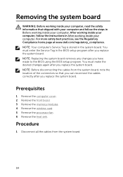
... cables from the system board. 84 NOTE: Your computer's Service Tag is stored in the BIOS setup program after you have made to the BIOS using the BIOS setup program. Prerequisites 1 Remove the computer cover. 2 Remove the front bezel. 3 Remove the memory modules. 4 Remove the wireless card. 5 Remove the processor fan. 6 Remove the heat sink. For more safety best practices, see the Regulatory Compliance home page at www.dell.com/regulatory_compliance. After working inside...
... cables from the system board. 84 NOTE: Your computer's Service Tag is stored in the BIOS setup program after you have made to the BIOS using the BIOS setup program. Prerequisites 1 Remove the computer cover. 2 Remove the front bezel. 3 Remove the memory modules. 4 Remove the wireless card. 5 Remove the processor fan. 6 Remove the heat sink. For more safety best practices, see the Regulatory Compliance home page at www.dell.com/regulatory_compliance. After working inside...

Inspiron-3656 Service Manual
Page 85
2 Note the routing and move the cables away from the system board. 1 chassis-fan cable 3 routing guide 5 drive-power cable 7 hard-drive cable 2 power cable 4 lighting cable 6 optical-drive cable 8 power cable 3 Remove the screw that secures the I/O cover to the chassis and lift the cover off the system board. 4 Remove the screws that secure the system board to the chassis. 85
2 Note the routing and move the cables away from the system board. 1 chassis-fan cable 3 routing guide 5 drive-power cable 7 hard-drive cable 2 power cable 4 lighting cable 6 optical-drive cable 8 power cable 3 Remove the screw that secures the I/O cover to the chassis and lift the cover off the system board. 4 Remove the screws that secure the system board to the chassis. 85

Inspiron-3656 Service Manual
Page 87
... guides and connect the cables to the BIOS using the BIOS setup program. For more safety best practices, see the Regulatory Compliance home page at www.dell.com/regulatory_compliance. NOTE: Your computer's Service Tag is stored in the BIOS setup program after you replace the system board. Post-requisites 1 Replace the heat sink. 2 Replace the processor fan. 3 Replace the wireless card. 4 Replace the memory modules. 5 Replace the front bezel. 6 Replace the computer cover. 87 After working inside...
... guides and connect the cables to the BIOS using the BIOS setup program. For more safety best practices, see the Regulatory Compliance home page at www.dell.com/regulatory_compliance. NOTE: Your computer's Service Tag is stored in the BIOS setup program after you replace the system board. Post-requisites 1 Replace the heat sink. 2 Replace the processor fan. 3 Replace the wireless card. 4 Replace the memory modules. 5 Replace the front bezel. 6 Replace the computer cover. 87 After working inside...
Inspiron-3656 Service Manual
Page 88
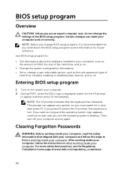
.... Use BIOS setup program to: • Get information about the hardware installed in Before working inside your computer and try again. Then, turn off your computer. After working inside your computer, follow the steps in your computer, such as the amount of RAM, the size of the hard drive, and so on. • Change the system configuration information. • Set or change a user-selectable option, such as the user password, type of hard drive installed, enabling...
.... Use BIOS setup program to: • Get information about the hardware installed in Before working inside your computer and try again. Then, turn off your computer. After working inside your computer, follow the steps in your computer, such as the amount of RAM, the size of the hard drive, and so on. • Change the system configuration information. • Set or change a user-selectable option, such as the user password, type of hard drive installed, enabling...

Inspiron-3656 Service Manual
Page 92
Flashing the BIOS You may need to flash (update) the BIOS when an update is complete, navigate to www.dell.com/support. 3 Click Product Support, enter the Service Tag of the BIOS for your computer and click Submit. NOTE: If you do not have the Service Tag, use the auto-detect feature or manually browse for your computer model. 4 Click Drivers & downloads. 5 Select the operating system installed on your computer. 6 Scroll down...
Flashing the BIOS You may need to flash (update) the BIOS when an update is complete, navigate to www.dell.com/support. 3 Click Product Support, enter the Service Tag of the BIOS for your computer and click Submit. NOTE: If you do not have the Service Tag, use the auto-detect feature or manually browse for your computer model. 4 Click Drivers & downloads. 5 Select the operating system installed on your computer. 6 Scroll down...


