Owners Manual
Page 19
...connector. Damage due to the system board, remove the main battery, see the Regulatory Compliance Homepage at support.dell.com/manuals for information on your computer. CAUTION: To help prevent damage to servicing that can increase your ...a connector on the type of the computer. Your computer has two user-accessible SODIMM sockets, labeled DIMM A and DIMM B, that is not authorized by Dell is not covered by your computer). NOTE: Memory modules purchased from the bottom of ... the system board. CAUTION: Only a certified service technician should perform repairs on page 15.
...connector. Damage due to the system board, remove the main battery, see the Regulatory Compliance Homepage at support.dell.com/manuals for information on your computer. CAUTION: To help prevent damage to servicing that can increase your ...a connector on the type of the computer. Your computer has two user-accessible SODIMM sockets, labeled DIMM A and DIMM B, that is not authorized by Dell is not covered by your computer). NOTE: Memory modules purchased from the bottom of ... the system board. CAUTION: Only a certified service technician should perform repairs on page 15.
Owners Manual
Page 41
...Assembly" on page 29. 4 Using a plastic scribe, gently pry the coin-cell out of the battery socket on the system board. 5 Lift the coin-cell battery out of the battery socket on the system board. Damage due to servicing that shipped with your warranty. CAUTION: To help prevent ...grounding strap or by your computer. 10 Coin-Cell Battery WARNING: Before working inside your computer, read the safety information that is not authorized by Dell is not covered by periodically touching an unpainted metal surface (such as a connector on your computer). See "Removing the Battery" on page 13....
...Assembly" on page 29. 4 Using a plastic scribe, gently pry the coin-cell out of the battery socket on the system board. 5 Lift the coin-cell battery out of the battery socket on the system board. Damage due to servicing that shipped with your warranty. CAUTION: To help prevent ...grounding strap or by your computer. 10 Coin-Cell Battery WARNING: Before working inside your computer, read the safety information that is not authorized by Dell is not covered by periodically touching an unpainted metal surface (such as a connector on your computer). See "Removing the Battery" on page 13....

Owners Manual
Page 42
... Coin-Cell Battery 1 Follow the instructions in "Before You Begin" on page 9. 2 With the positive side up, snap the coin-cell battery into the battery socket on the system board. 3 Follow the instructions from step 3 to step 7 in damage to do so may result in "Replacing the Palm-Rest Assembly" on...
... Coin-Cell Battery 1 Follow the instructions in "Before You Begin" on page 9. 2 With the positive side up, snap the coin-cell battery into the battery socket on the system board. 3 Follow the instructions from step 3 to step 7 in damage to do so may result in "Replacing the Palm-Rest Assembly" on...
Owners Manual
Page 47
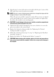
...on page 29. 4 Remove the thermal cooling assembly. 13 Processor Module (For Inspiron 15-N5050/15-N5040 Only) WARNING: Before working inside your computer, read the safety information that is not authorized by Dell is not covered by their edges, and avoid touching pins and contacts. For additional... safety best practices information, see "Removing the Battery" on page 45. 5 To loosen the ZIF socket, use a small, flat-blade screwdriver and rotate the ZIF-socket cam screw ...
...on page 29. 4 Remove the thermal cooling assembly. 13 Processor Module (For Inspiron 15-N5050/15-N5040 Only) WARNING: Before working inside your computer, read the safety information that is not authorized by Dell is not covered by their edges, and avoid touching pins and contacts. For additional... safety best practices information, see "Removing the Battery" on page 45. 5 To loosen the ZIF socket, use a small, flat-blade screwdriver and rotate the ZIF-socket cam screw ...
Owners Manual
Page 48
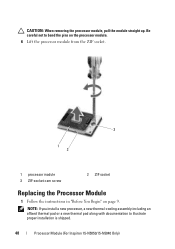
NOTE: If you install a new processor, a new thermal-cooling assembly including an affixed thermal pad or a new thermal pad along with documentation to bend the pins on the processor module. 6 Lift the processor module from the ZIF socket. 3 1 2 1 processor module 3 ZIF-socket cam screw 2 ZIF socket Replacing the Processor Module 1 Follow the instructions in "Before You Begin" on page 9. CAUTION: When removing the processor module, pull the module straight up. Be careful not to illustrate proper installation is shipped. 48 Processor Module (For Inspiron 15-N5050/15-N5040 Only)
NOTE: If you install a new processor, a new thermal-cooling assembly including an affixed thermal pad or a new thermal pad along with documentation to bend the pins on the processor module. 6 Lift the processor module from the ZIF socket. 3 1 2 1 processor module 3 ZIF-socket cam screw 2 ZIF socket Replacing the Processor Module 1 Follow the instructions in "Before You Begin" on page 9. CAUTION: When removing the processor module, pull the module straight up. Be careful not to illustrate proper installation is shipped. 48 Processor Module (For Inspiron 15-N5050/15-N5040 Only)
Owners Manual
Page 49
...battery. CAUTION: To avoid damage to the processor, hold the screwdriver perpendicular to the processor when turning the cam screw. 3 Tighten the ZIF socket by turning the cam screw clockwise to secure the processor module to step 7 in damage to the computer. See "Replacing the Thermal Cooling ...corner of the processor module with the triangle on the pin-1 corner of the ZIF socket. NOTE: The pin-1 corner of the ZIF socket, then insert the processor module. Processor Module (For Inspiron 15-N5050/15-N5040 Only) 49 CAUTION: Before turning on the computer, replace all four corners are...
...battery. CAUTION: To avoid damage to the processor, hold the screwdriver perpendicular to the processor when turning the cam screw. 3 Tighten the ZIF socket by turning the cam screw clockwise to secure the processor module to step 7 in damage to the computer. See "Replacing the Thermal Cooling ...corner of the processor module with the triangle on the pin-1 corner of the ZIF socket. NOTE: The pin-1 corner of the ZIF socket, then insert the processor module. Processor Module (For Inspiron 15-N5050/15-N5040 Only) 49 CAUTION: Before turning on the computer, replace all four corners are...


