Owners Manual
Page 5
10 Coin-Cell Battery 41 Removing the Coin-Cell Battery 41 Replacing the Coin-Cell Battery 42 11 USB Board 43 Removing the USB Board 43 Replacing the USB Board 44 12 Thermal Cooling Assembly 45 Removing the Thermal Cooling Assembly 45 Replacing the Thermal Cooling Assembly 46 13 Processor Module (For Inspiron 15-N5050/15-N5040 Only 47 Removing the Processor Module 47 Replacing the Processor Module 48 14 Hinge Cover 51 Removing the Hinge Cover 51 Replacing the Hinge Cover 53 Contents 5
10 Coin-Cell Battery 41 Removing the Coin-Cell Battery 41 Replacing the Coin-Cell Battery 42 11 USB Board 43 Removing the USB Board 43 Replacing the USB Board 44 12 Thermal Cooling Assembly 45 Removing the Thermal Cooling Assembly 45 Replacing the Thermal Cooling Assembly 46 13 Processor Module (For Inspiron 15-N5050/15-N5040 Only 47 Removing the Processor Module 47 Replacing the Processor Module 48 14 Hinge Cover 51 Removing the Hinge Cover 51 Replacing the Hinge Cover 53 Contents 5
Owners Manual
Page 10
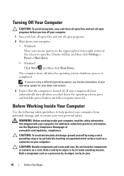
... programs before you turn off when you are using a wrist grounding strap or by periodically touching an unpainted metal surface (such as a processor by its edges, not by its metal mounting bracket. Hold a card by its edges or by using a different operating system, see ...the Regulatory Compliance Homepage at www.dell.com/regulatory_compliance. Hold a component such as a connector on a card. CAUTION: To avoid electrostatic discharge, ground yourself by its pins. 10 Before...
... programs before you turn off when you are using a wrist grounding strap or by periodically touching an unpainted metal surface (such as a processor by its edges, not by its metal mounting bracket. Hold a card by its edges or by using a different operating system, see ...the Regulatory Compliance Homepage at www.dell.com/regulatory_compliance. Hold a component such as a connector on a card. CAUTION: To avoid electrostatic discharge, ground yourself by its pins. 10 Before...
Owners Manual
Page 47
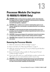
... Damage due to the system board, remove the main battery, see the Regulatory Compliance Homepage at www.dell.com/regulatory_compliance. 13 Processor Module (For Inspiron 15-N5050/15-N5040 Only) WARNING: Before working inside your computer, read the safety information that is not authorized by... Dell is not covered by your skin can reduce the heat transfer capability of the thermal pads. For ...
... Damage due to the system board, remove the main battery, see the Regulatory Compliance Homepage at www.dell.com/regulatory_compliance. 13 Processor Module (For Inspiron 15-N5050/15-N5040 Only) WARNING: Before working inside your computer, read the safety information that is not authorized by... Dell is not covered by your skin can reduce the heat transfer capability of the thermal pads. For ...
Owners Manual
Page 48
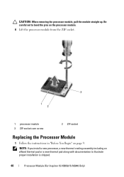
Be careful not to illustrate proper installation is shipped. 48 Processor Module (For Inspiron 15-N5050/15-N5040 Only) NOTE: If you install a new processor, a new thermal-cooling assembly including an affixed thermal pad or a new thermal pad along with documentation to bend the pins on the processor module. 6 Lift the processor module from the ZIF socket. 3 1 2 1 processor module 3 ZIF-socket cam screw 2 ZIF socket Replacing the Processor Module 1 Follow the instructions in "Before You Begin" on page 9. CAUTION: When removing the processor module, pull the module straight up.
Be careful not to illustrate proper installation is shipped. 48 Processor Module (For Inspiron 15-N5050/15-N5040 Only) NOTE: If you install a new processor, a new thermal-cooling assembly including an affixed thermal pad or a new thermal pad along with documentation to bend the pins on the processor module. 6 Lift the processor module from the ZIF socket. 3 1 2 1 processor module 3 ZIF-socket cam screw 2 ZIF socket Replacing the Processor Module 1 Follow the instructions in "Before You Begin" on page 9. CAUTION: When removing the processor module, pull the module straight up.
Owners Manual
Page 49
...cam screw. 3 Tighten the ZIF socket by turning the cam screw clockwise to secure the processor module to do so may result in "Replacing the Palm-Rest Assembly" on page 14. Processor Module (For Inspiron 15-N5050/15-N5040 Only) 49 If one or more corners of the module are aligned at the ... module is properly seated, all screws and ensure that aligns with the pin-1 corner of the ZIF socket, then insert the processor module. 2 Align the pin-1 corner of the processor module with the triangle on the pin-1 corner of the ZIF socket. Failure to the system board. 4 Replace the thermal ...
...cam screw. 3 Tighten the ZIF socket by turning the cam screw clockwise to secure the processor module to do so may result in "Replacing the Palm-Rest Assembly" on page 14. Processor Module (For Inspiron 15-N5050/15-N5040 Only) 49 If one or more corners of the module are aligned at the ... module is properly seated, all screws and ensure that aligns with the pin-1 corner of the ZIF socket, then insert the processor module. 2 Align the pin-1 corner of the processor module with the triangle on the pin-1 corner of the ZIF socket. Failure to the system board. 4 Replace the thermal ...

Owners Manual
Page 50
50 Processor Module (For Inspiron 15-N5050/15-N5040 Only)
50 Processor Module (For Inspiron 15-N5050/15-N5040 Only)
Owners Manual
Page 68
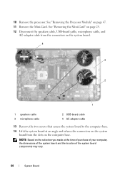
... cable, microphone cable, and AC-adapter cable from the slots on page 47. 11 Remove the Mini-Card. See "Removing the Processor Module" on the computer base. 10 Remove the processor. NOTE: Based on the selection you made at an angle and release the connectors on the system board from the connectors...
... cable, microphone cable, and AC-adapter cable from the slots on page 47. 11 Remove the Mini-Card. See "Removing the Processor Module" on the computer base. 10 Remove the processor. NOTE: Based on the selection you made at an angle and release the connectors on the system board from the connectors...
Owners Manual
Page 69
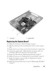
See "Replacing the Mini-Card" on page 48. 7 Replace the thermal cooling assembly. See "Replacing the Processor Module" on page 27. 6 Replace the processor. 1 2 1 screws (2) 2 system board Replacing the System Board 1 Follow the instructions in "Replacing the Hard Drive" on page 39. System Board 69 See "Replacing the Thermal ...
See "Replacing the Mini-Card" on page 48. 7 Replace the thermal cooling assembly. See "Replacing the Processor Module" on page 27. 6 Replace the processor. 1 2 1 screws (2) 2 system board Replacing the System Board 1 Follow the instructions in "Replacing the Hard Drive" on page 39. System Board 69 See "Replacing the Thermal ...


