
Owners Manual
Page 57
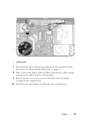
See "Removing the Mini-Card" on page 25. 8 Make a note of the display cable and Mini-Card antenna cables routing and remove the cables from the connectors on each side) that secure the display assembly to the computer base. 10 Lift and remove the display assembly out of the computer base. Display 57 1 1 display cable 7 Disconnect the Mini-Card antenna cables from the routing guides. 9 Remove the four screws (two on the Mini-Card.
See "Removing the Mini-Card" on page 25. 8 Make a note of the display cable and Mini-Card antenna cables routing and remove the cables from the connectors on each side) that secure the display assembly to the computer base. 10 Lift and remove the display assembly out of the computer base. Display 57 1 1 display cable 7 Disconnect the Mini-Card antenna cables from the routing guides. 9 Remove the four screws (two on the Mini-Card.
Owners Manual
Page 68
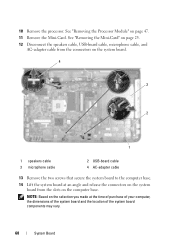
See "Removing the Mini-Card" on page 25. 12 Disconnect the speakers cable, USB-board cable, microphone cable, and AC-adapter cable from the connectors on the system board. 4 3 2 1 1 ... on the selection you made at an angle and release the connectors on the system board from the slots on page 47. 11 Remove the Mini-Card. See "Removing the Processor Module" on the computer base...
See "Removing the Mini-Card" on page 25. 12 Disconnect the speakers cable, USB-board cable, microphone cable, and AC-adapter cable from the connectors on the system board. 4 3 2 1 1 ... on the selection you made at an angle and release the connectors on the system board from the slots on page 47. 11 Remove the Mini-Card. See "Removing the Processor Module" on the computer base...


