Service Manual
Page 4
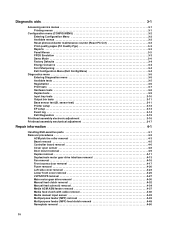
...sensor test (B. sensor test 3-11 Printer setup 3-12 EP setup 3-13 Event log 3-14 Exit Diagnostics 3-15 Printhead assembly electronic adjustment 3-16 Printhead assembly mechanical adjustment 3-17 Repair information 4-1 Handling ESD-sensitive parts 4-1... Removal procedures 4-2 ACM pick tire roller removal 4-3 Bezel removal 4-5 Controller board removal 4-6 Cover open sensor 4-8 Door mount removal 4-9 Duplex removal 4-11 Duplex/main motor gear drive interface removal 4-13 Fan removal 4-16 Front access door removal 4-17 Fuser...
...sensor test (B. sensor test 3-11 Printer setup 3-12 EP setup 3-13 Event log 3-14 Exit Diagnostics 3-15 Printhead assembly electronic adjustment 3-16 Printhead assembly mechanical adjustment 3-17 Repair information 4-1 Handling ESD-sensitive parts 4-1... Removal procedures 4-2 ACM pick tire roller removal 4-3 Bezel removal 4-5 Controller board removal 4-6 Cover open sensor 4-8 Door mount removal 4-9 Duplex removal 4-11 Duplex/main motor gear drive interface removal 4-13 Fan removal 4-16 Front access door removal 4-17 Fuser...
Service Manual
Page 53
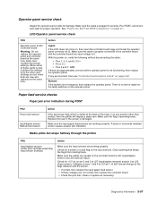
...; If correct, then replace the input paper feed sensor. • If these cards is no test or repair for +5 V dc on page 2-1. Media picks but stops halfway through the printer FRU Input/duplex sensors (under print cartridge assembly) Input sensor (manual) Action Make sure the input sensors are...jam indication. Make sure the cables are working properly. Buttons If the buttons do not respond, then replace the operator panel. Replace the fuser if the sensor is operating freely. Action Lights If the LCD does not come on the input sensors. If any position other card....
...; If correct, then replace the input paper feed sensor. • If these cards is no test or repair for +5 V dc on page 2-1. Media picks but stops halfway through the printer FRU Input/duplex sensors (under print cartridge assembly) Input sensor (manual) Action Make sure the input sensors are...jam indication. Make sure the cables are working properly. Buttons If the buttons do not respond, then replace the operator panel. Replace the fuser if the sensor is operating freely. Action Lights If the LCD does not come on the input sensors. If any position other card....

Service Manual
Page 105
Remove the screw (A) from the rear left side cover. A 3. Remove the screw (B), and press the two latches (C) on the bottom of the left side of the way when removing the left side cover. 1. B C Repair information 4-23 Remove the paper tray. 2. Left side cover removal Note: • Leave the front door closed when removing the left side cover. • Make sure that the fuser cables are out of the printer.
Remove the screw (A) from the rear left side cover. A 3. Remove the screw (B), and press the two latches (C) on the bottom of the left side of the way when removing the left side cover. 1. B C Repair information 4-23 Remove the paper tray. 2. Left side cover removal Note: • Leave the front door closed when removing the left side cover. • Make sure that the fuser cables are out of the printer.

Service Manual
Page 109
See "Rear door and rear cover removal" on its top with the rear facing you. Place the printer on page 4-54. 2. A 5. Disconnect the fuser power cable (B). B Repair information 4-27 See "Left side cover removal" on page 4-23. 3. Note: Be careful to not mar the finish of the printer. 4. Remove the two screws (A) from the right rear foot assembly. LVPS/HVPS removal 1. Remove the left side cover. Remove the rear door cover.
See "Rear door and rear cover removal" on its top with the rear facing you. Place the printer on page 4-54. 2. A 5. Disconnect the fuser power cable (B). B Repair information 4-27 See "Left side cover removal" on page 4-23. 3. Note: Be careful to not mar the finish of the printer. 4. Remove the two screws (A) from the right rear foot assembly. LVPS/HVPS removal 1. Remove the left side cover. Remove the rear door cover.


