Product Manual
Page 2
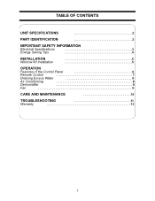
TABLE OF CONTENTS UNIT SPECIFICATIONS 2 PART IDENTIFICATION 3 IMPORTANT SAFETY INFORMATION Electrical Specifications 3 Energy Saving Tips 4 INSTALLATION Window Kit Installation 5 5 OPERATION Features of the Control Panel 6 Remote Control 7 Draining Excess Water 8 Air Conditioning 8 Dehumidifier 9 Fan 9 CARE AND MAINTENANCE 10 TROUBLESHOOTING 11 Warranty 12 1
TABLE OF CONTENTS UNIT SPECIFICATIONS 2 PART IDENTIFICATION 3 IMPORTANT SAFETY INFORMATION Electrical Specifications 3 Energy Saving Tips 4 INSTALLATION Window Kit Installation 5 5 OPERATION Features of the Control Panel 6 Remote Control 7 Draining Excess Water 8 Air Conditioning 8 Dehumidifier 9 Fan 9 CARE AND MAINTENANCE 10 TROUBLESHOOTING 11 Warranty 12 1
Product Manual
Page 3
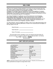
..." air swing capabilities. This unit can be necessary if your home and set up in steady improvement. To contact a Customer Service Representative, call Danby TOLL FREE: 1-800-26- (1800-263-2629) UNIT SPECIFICATIONS Unit Specifications Model Number Voltage/Frequency Noise Level Fan Speeds Airflow CFM High / Medium... servicing and/or for the proper care and maintenance of your home, cottage, or office. Model Number: Serial Number: Date of Day Clock Auto-Timer DPAC7099 115V-60Hz 50 dB 3 282 / 252 / 222 7000BTU R410A 24.5 kg (53.9 lbs) 17 1/3"x 12"x 27 1/6" 440 x 305 x 690 Yes ...
..." air swing capabilities. This unit can be necessary if your home and set up in steady improvement. To contact a Customer Service Representative, call Danby TOLL FREE: 1-800-26- (1800-263-2629) UNIT SPECIFICATIONS Unit Specifications Model Number Voltage/Frequency Noise Level Fan Speeds Airflow CFM High / Medium... servicing and/or for the proper care and maintenance of your home, cottage, or office. Model Number: Serial Number: Date of Day Clock Auto-Timer DPAC7099 115V-60Hz 50 dB 3 282 / 252 / 222 7000BTU R410A 24.5 kg (53.9 lbs) 17 1/3"x 12"x 27 1/6" 440 x 305 x 690 Yes ...
Product Manual
Page 4
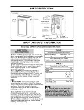
If it is necessary to a failed unit are properly grounded, please consult a qualified electrician. If you have any properly wired, general purpose 15 amp household grounded receptacle. 3) For your home are located. TABLE 2 Receptacle and Fuse Types Rated Volts 125 Amps 15 Wall Outlet Fuse Size Time Delay Fuse (or Circuit Breaker) 15 Plug Type CAUTION: Do not leave this unit is proplery grounded. 4) DO NOT USE PLUG ADAPTERS OR EXTENSION CORDS WITH THIS UNIT. A failed unit can result in risk of Fire, Electric Shock, and/or injury to the unit before installing and/or ...
If it is necessary to a failed unit are properly grounded, please consult a qualified electrician. If you have any properly wired, general purpose 15 amp household grounded receptacle. 3) For your home are located. TABLE 2 Receptacle and Fuse Types Rated Volts 125 Amps 15 Wall Outlet Fuse Size Time Delay Fuse (or Circuit Breaker) 15 Plug Type CAUTION: Do not leave this unit is proplery grounded. 4) DO NOT USE PLUG ADAPTERS OR EXTENSION CORDS WITH THIS UNIT. A failed unit can result in risk of Fire, Electric Shock, and/or injury to the unit before installing and/or ...
Product Manual
Page 5
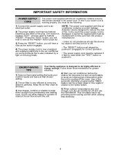
..." button must always be pushed in . IMPORTANT SAFETY INFORMATION POWER SUPPLY CORD The power cord supplied with this is marked "RESET". ENERGY-SAVING TIPS Your Danby appliance is pushed in (engaged) for greater efficiency. 1) Select a thermostat setting that chosen setting. 2) The air filter is cooling off and use the FAN MODE...
..." button must always be pushed in . IMPORTANT SAFETY INFORMATION POWER SUPPLY CORD The power cord supplied with this is marked "RESET". ENERGY-SAVING TIPS Your Danby appliance is pushed in (engaged) for greater efficiency. 1) Select a thermostat setting that chosen setting. 2) The air filter is cooling off and use the FAN MODE...
Product Manual
Page 6
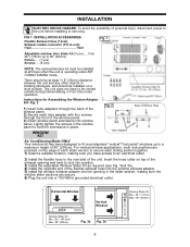
from 28 1/3"(72cm) up to a maximum height of 80" (203cm). Insert the hose collar on top of the exhaust opening and twist to lock into position. 3) Install the adjustable Window Slider Kit as required (see Fig. 3a & 3b). 4) Install the opposite end of the flexible exhaust hose into the window exhaust adapter. 5) Install the window exhaust adapter into the opening in the slider section, making sure you have to the unit before installing or servicing. INSTALLATION ACCESSORIES Flexible Exhaust Hose (13cm), Exhaust nozzle connector (Fix to hold the extensions in the window panel to unit...
from 28 1/3"(72cm) up to a maximum height of 80" (203cm). Insert the hose collar on top of the exhaust opening and twist to lock into position. 3) Install the adjustable Window Slider Kit as required (see Fig. 3a & 3b). 4) Install the opposite end of the flexible exhaust hose into the window exhaust adapter. 5) Install the window exhaust adapter into the opening in the slider section, making sure you have to the unit before installing or servicing. INSTALLATION ACCESSORIES Flexible Exhaust Hose (13cm), Exhaust nozzle connector (Fix to hold the extensions in the window panel to unit...
Product Manual
Page 7
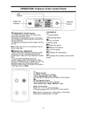
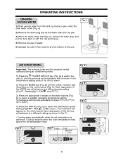
Note: When the unit is invalid. 6 The running mode and fan speed mode will be set automatically. • Pressing the emergency button again will be that which was in operation before water full indicator illumination. • LED light colour is used when unit needs to be discharged and the condensation water level has reached full water level. • The unit stops operating when this indicator flashes. WATER FULL INDICATOR • When illuminated, signifies condensed water inside the unit can't be temporarily switched on/off. • Pressing the emergency will turn on , remember ...
Note: When the unit is invalid. 6 The running mode and fan speed mode will be set automatically. • Pressing the emergency button again will be that which was in operation before water full indicator illumination. • LED light colour is used when unit needs to be discharged and the condensation water level has reached full water level. • The unit stops operating when this indicator flashes. WATER FULL INDICATOR • When illuminated, signifies condensed water inside the unit can't be temporarily switched on/off. • Pressing the emergency will turn on , remember ...
Product Manual
Page 8
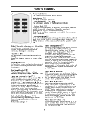
If room temperature is higher than 25°C (77°F), fan speed can be shown in the display together with the clock symbol and the "ON" logo. Set Controls & The temperature can be shown in the display together with the clock symbol and "OFF" logo. The temperature can be set temperature to remain in the display panel for either on the machine itself or on the remote control) so that the timer is not required, pressing the CANCEL button will switch the display between 00 and 24) for approximately 5 seconds. Fahrenheit/Celsius Selector Pressing this button will turn ...
If room temperature is higher than 25°C (77°F), fan speed can be shown in the display together with the clock symbol and the "ON" logo. Set Controls & The temperature can be shown in the display together with the clock symbol and "OFF" logo. The temperature can be set temperature to remain in the display panel for either on the machine itself or on the remote control) so that the timer is not required, pressing the CANCEL button will switch the display between 00 and 24) for approximately 5 seconds. Fahrenheit/Celsius Selector Pressing this button will turn ...
Product Manual
Page 9
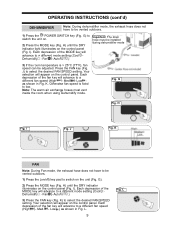
C). Fan - D) to select the desired fan speed setting (High - Cooling resumes when the room temperature rises above the set temperature is achieved. Each depression of the control panel. 2) Press the MODE key (Fig. Auto ) 3) Press the appropriate increase or decrease buttons (Fig. E) to select a suitable operating temperature setting. Dehumidify - Temperature settings are adjustable between 16°C (61°F) to switch the unit on the control panel (Fig. C Fig. B) until the COOL indicator light illuminates on , and the previous set temperature will advance to ...
C). Fan - D) to select the desired fan speed setting (High - Cooling resumes when the room temperature rises above the set temperature is achieved. Each depression of the control panel. 2) Press the MODE key (Fig. Auto ) 3) Press the appropriate increase or decrease buttons (Fig. E) to select a suitable operating temperature setting. Dehumidify - Temperature settings are adjustable between 16°C (61°F) to switch the unit on the control panel (Fig. C Fig. B) until the COOL indicator light illuminates on , and the previous set temperature will advance to ...
Product Manual
Page 10
J) to low. Low ) as shown in Fig. K. G Fig. H) until the DRY indicator light illuminates on the control panel (Fig. Your selection will appear on the control panel. Auto ) Important: The drain hose must vent inside the room when using Dehumidify mode. Your selection will appear on the control panel. Fig. L. 9 Fig. Press the FAN key (Fig. Otherwise fan speed is > 25°C (77°F), fan speed can be installed during dehumidifier mode 3) If the room temperature is fixed to select the desired FAN SPEED setting. Auto ) 3) Press the FAN ...
J) to low. Low ) as shown in Fig. K. G Fig. H) until the DRY indicator light illuminates on the control panel (Fig. Your selection will appear on the control panel. Auto ) Important: The drain hose must vent inside the room when using Dehumidify mode. Your selection will appear on the control panel. Fig. L. 9 Fig. Press the FAN key (Fig. Otherwise fan speed is > 25°C (77°F), fan speed can be installed during dehumidifier mode 3) If the room temperature is fixed to select the desired FAN SPEED setting. Auto ) 3) Press the FAN ...
Product Manual
Page 11
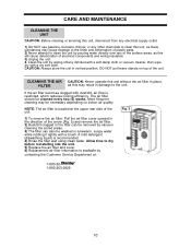
Allow time to dry before reinstalling into the unit. 5) Replace the air filter and cover. 6) Replacement air filter information is available by vacuum cleaning the soiled areas. 3) The filter can be washed in lukewarm, soapy water while rubbing it lightly with a brush. DO NOT put heavy objects on indoor air quality. Clean the unit by wiping off any of the surface areas, as this may result in damage to the unit. CAUTION: Always store the unit in place, FILTER as this will cause deterioration of electrical components and wiring insulation. 3) Unplug the unit. 4. If the...
Allow time to dry before reinstalling into the unit. 5) Replace the air filter and cover. 6) Replacement air filter information is available by vacuum cleaning the soiled areas. 3) The filter can be washed in lukewarm, soapy water while rubbing it lightly with a brush. DO NOT put heavy objects on indoor air quality. Clean the unit by wiping off any of the surface areas, as this may result in damage to the unit. CAUTION: Always store the unit in place, FILTER as this will cause deterioration of electrical components and wiring insulation. 3) Unplug the unit. 4. If the...
Product Manual
Page 12
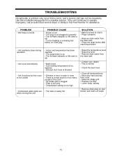
...; There is a heat source or too many people in properly • The full-tank indicator is minor, and a service call an authorized service depot or Danby's Toll Free Number for a possible solution. setting • Remove drain plug on LCDI plug SOLUTION • Wait for power to operate improperly, call may not...
...; There is a heat source or too many people in properly • The full-tank indicator is minor, and a service call an authorized service depot or Danby's Toll Free Number for a possible solution. setting • Remove drain plug on LCDI plug SOLUTION • Wait for power to operate improperly, call may not...