Product Manual
Page 1
All rights reserved. Web/Installation Guide Product Model: TM DWS/DXS-3200 Series Layer 2+ Stackable Gigabit Ethernet Switches with optional XG uplinks Release 2.0 ©Copyright 2006.
All rights reserved. Web/Installation Guide Product Model: TM DWS/DXS-3200 Series Layer 2+ Stackable Gigabit Ethernet Switches with optional XG uplinks Release 2.0 ©Copyright 2006.
Product Manual
Page 2
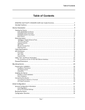
Table of Contents Table of Contents DXS/DWS-3227/3227P, DXS/DWS-3250 User Guide Overview 7 Intended Audience...8 Device Description ...9 Viewing the Device ...9 DXS-3250/DWS Front Panel ...9 DXS/DWS-3227 Front Panel ...10 DXS/DWS-3227P Front Panel...10 Back Panels...11 Ports Description ...12 1000Base-T Gigabit Ethernet ... Installing the Device ...27 Desktop or Shelf Installation ...27 Rack Installation ...27 Connecting the Device ...30 Connecting the Switch to a Terminal ...30 AC Power Connection ...30 Initial Configuration ...31 General Configuration Information 31 Auto-Negotiation ...31 Device...
Table of Contents Table of Contents DXS/DWS-3227/3227P, DXS/DWS-3250 User Guide Overview 7 Intended Audience...8 Device Description ...9 Viewing the Device ...9 DXS-3250/DWS Front Panel ...9 DXS/DWS-3227 Front Panel ...10 DXS/DWS-3227P Front Panel...10 Back Panels...11 Ports Description ...12 1000Base-T Gigabit Ethernet ... Installing the Device ...27 Desktop or Shelf Installation ...27 Rack Installation ...27 Connecting the Device ...30 Connecting the Switch to a Terminal ...30 AC Power Connection ...30 Initial Configuration ...31 General Configuration Information 31 Auto-Negotiation ...31 Device...
Product Manual
Page 3
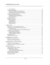
DXS/DSW 3200 Series User Guide Initial Configuration ...35 Advanced Configuration...38 Retrieving an IP Address From ...Password Recovery ...48 WLAN Licence Key ...48 Getting Started...51 Starting the D-Link Embedded Web Interface 52 Understanding the D-Link Embedded Web Interface 54 Device Representation...55 Using the D-Link Embedded Web Interface Management Buttons 56 Using Screen and Table Options 57 Adding Configuration... and Unit ID ...72 Removing and Replacing Stacking Members 73 Exchanging Stacking Members...74 Switching the Stacking Master ...74 Configuring Stacking ...75 Page 2
DXS/DSW 3200 Series User Guide Initial Configuration ...35 Advanced Configuration...38 Retrieving an IP Address From ...Password Recovery ...48 WLAN Licence Key ...48 Getting Started...51 Starting the D-Link Embedded Web Interface 52 Understanding the D-Link Embedded Web Interface 54 Device Representation...55 Using the D-Link Embedded Web Interface Management Buttons 56 Using Screen and Table Options 57 Adding Configuration... and Unit ID ...72 Removing and Replacing Stacking Members 73 Exchanging Stacking Members...74 Switching the Stacking Master ...74 Configuring Stacking ...75 Page 2
Product Manual
Page 5
DXS/DSW 3200 Series User Guide Viewing WLAN Stations ...169 Configuring IP Information 171 Configuring IP Interfaces...171 Defining IP Addresses ...172 Defining Default Gateways ...174 ...
DXS/DSW 3200 Series User Guide Viewing WLAN Stations ...169 Configuring IP Information 171 Configuring IP Interfaces...171 Defining IP Addresses ...172 Defining Default Gateways ...174 ...
Product Manual
Page 7
DXS/DSW 3200 Series User Guide Configuring System Time...281 Configuring Daylight Savings Time 281 Configuring SNTP ...285 Polling for Unicast Time Information ...285 Polling for ... ...308 Defining RMON Alarms...315 Appendix A, WLAN Country Settings 317 Appendix B, Device Specifications & Features 325 Appendix B, Troubleshooting 333 Problem Management...334 Troubleshooting Solutions...334 Contacting D-Link Technical Support 337 Warranty...365 Product Registration...369 International Offices ...371 Page 6
DXS/DSW 3200 Series User Guide Configuring System Time...281 Configuring Daylight Savings Time 281 Configuring SNTP ...285 Polling for Unicast Time Information ...285 Polling for ... ...308 Defining RMON Alarms...315 Appendix A, WLAN Country Settings 317 Appendix B, Device Specifications & Features 325 Appendix B, Troubleshooting 333 Problem Management...334 Troubleshooting Solutions...334 Contacting D-Link Technical Support 337 Warranty...365 Product Registration...369 International Offices ...371 Page 6
Product Manual
Page 8
..., monitors, and troubleshoots network devices from a remote web browser. The D-Link Web System Interface User Guide provides the following sections: • DXS/DWS-3227/3227P, DXS/DWS-3250 User Guide Overview • Intended Audience DXS/DWS-3227/3227P, DXS/DWS-3250 User Guide Overview This section provides an overview to the D-Link Embedded Interface User Guide, and includes the following sections: •...
..., monitors, and troubleshoots network devices from a remote web browser. The D-Link Web System Interface User Guide provides the following sections: • DXS/DWS-3227/3227P, DXS/DWS-3250 User Guide Overview • Intended Audience DXS/DWS-3227/3227P, DXS/DWS-3250 User Guide Overview This section provides an overview to the D-Link Embedded Interface User Guide, and includes the following sections: •...
Product Manual
Page 9
... RMON sta- Provides information about configuring system time, including Daylight Savings Time parameters and Simple Network Time Protocol (SNTP) parameters. • Section 23, Viewing Statistics - DXS/DWS 3200 Series User Guide • Section 18, Configuring Quality of Service on the device. • Section 19, Managing System Files - Intended Audience This guide is...
... RMON sta- Provides information about configuring system time, including Daylight Savings Time parameters and Simple Network Time Protocol (SNTP) parameters. • Section 23, Viewing Statistics - DXS/DWS 3200 Series User Guide • Section 18, Configuring Quality of Service on the device. • Section 19, Managing System Files - Intended Audience This guide is...
Product Manual
Page 10
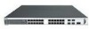
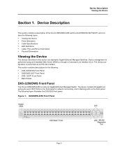
... a description of the D-Link DWS/DXS-3250 and D-Link DWS/DXS-3227/3227P, and contains the following topics: • Viewing the Device • Ports Description • Cable Specifications • LED Definitions • Cable, Port, and Pinout Information • Physical Dimensions Viewing the Device The devices described in this section are stackable Gigabit Ethernet Managed Switches. Device Description Viewing the...
... a description of the D-Link DWS/DXS-3250 and D-Link DWS/DXS-3227/3227P, and contains the following topics: • Viewing the Device • Ports Description • Cable Specifications • LED Definitions • Cable, Port, and Pinout Information • Physical Dimensions Viewing the Device The devices described in this section are stackable Gigabit Ethernet Managed Switches. Device Description Viewing the...
Product Manual
Page 11
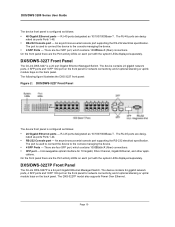
..., Gigabit Ethernet, and other appli- The RJ-45 ports are desig- There are the Port activity LEDs on the back panel. DXS/DWS-3227P Front Panel The D-Link DXS-3227P is a 24 port Gigabit Ethernet Managed Switch. On the front panel there are four SFP port, which contains 1000Base-X (fiber) connections. An asynchronous serial console port supporting...
..., Gigabit Ethernet, and other appli- The RJ-45 ports are desig- There are the Port activity LEDs on the back panel. DXS/DWS-3227P Front Panel The D-Link DXS-3227P is a 24 port Gigabit Ethernet Managed Switch. On the front panel there are four SFP port, which contains 1000Base-X (fiber) connections. An asynchronous serial console port supporting...
Product Manual
Page 12
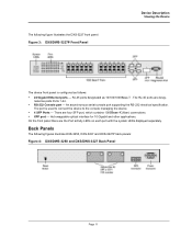
... separately. An asynchronous serial console port supporting the RS-232 electrical specification. Back Panels The following figure illustrates the DXS-3227 front panel: Figure 3: DXS/DWS-3227P Front Panel Device Description Viewing the Device The device front panel is used to connect the device to the console ...• RS-232 Console port - The port is configured as follows: • 24 Gigabit Ethernet ports - The following figures illustrate DXS-3250, DXS-3227 and DXS-3227P back panels: Figure 4: DXS/DWS-3250 and DXS/DWS-3227 Back Panel Page 11 nated as 10/100/1000Base-T .
... separately. An asynchronous serial console port supporting the RS-232 electrical specification. Back Panels The following figure illustrates the DXS-3227 front panel: Figure 3: DXS/DWS-3227P Front Panel Device Description Viewing the Device The device front panel is used to connect the device to the console ...• RS-232 Console port - The port is configured as follows: • 24 Gigabit Ethernet ports - The following figures illustrate DXS-3250, DXS-3227 and DXS-3227P back panels: Figure 4: DXS/DWS-3250 and DXS/DWS-3227 Back Panel Page 11 nated as 10/100/1000Base-T .
Product Manual
Page 13
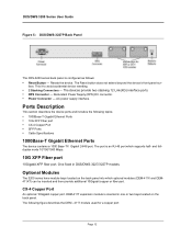
... Gigabit Ethernet Ports The device contains a 1000 Base-TX Gigabit 24/48 port. AC power supply interface. DXS/DWS 3200 Series User Guide Figure 5: DXS/DWS-3227P Back Panel The DXS-3200 series back panel is configured as follows: • Reset Button - Resets the device. The Reset button... does not extend beyond the device's front panel sur- The devices provide two stacking 12 Link(XG) interface ports. &#...
... Gigabit Ethernet Ports The device contains a 1000 Base-TX Gigabit 24/48 port. AC power supply interface. DXS/DWS 3200 Series User Guide Figure 5: DXS/DWS-3227P Back Panel The DXS-3200 series back panel is configured as follows: • Reset Button - Resets the device. The Reset button... does not extend beyond the device's front panel sur- The devices provide two stacking 12 Link(XG) interface ports. &#...
Product Manual
Page 15
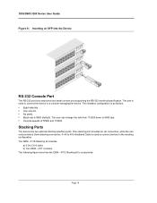
... to connect the device to connect devices in the stacking configuration. One stacking port provides an Up connection, while the second provides a Down stacking connection. DXS/DWS 3200 Series User Guide Figure 8: Inserting an SFP into the Device RS-232 Console Port The RS-232 port is 9600 (default). Stacking Ports The...
... to connect the device to connect devices in the stacking configuration. One stacking port provides an Up connection, while the second provides a Down stacking connection. DXS/DWS 3200 Series User Guide Figure 8: Inserting an SFP into the Device RS-232 Console Port The RS-232 port is 9600 (default). Stacking Ports The...
Product Manual
Page 17
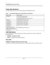
...are as follows: • Port LEDs - Indicate SFP port status. • System - Page 16 DXS/DWS 3200 Series User Guide Cable Specifications The following figure illustrates the DXS-3250 port LEDs. Indicating the device power supply status. Indicate each port status. • SFP Ports ...(100 meters max.) EIA/TIA-568B 150-ohm STP (100 meters max.) 10Gigabit copper port (Up to the D-Link datasheet for the DXS/DWS-3200 series: Table 1: DXS-3250/DXS-3227P Cables and Optical Modules Specifications Cable Type 1000Base-T 10G CX-4 1000BASE-LX 1000BASE-SX 1000BASE-LH 1000BASE-ZX 10Gigabit -
...are as follows: • Port LEDs - Indicate SFP port status. • System - Page 16 DXS/DWS 3200 Series User Guide Cable Specifications The following figure illustrates the DXS-3250 port LEDs. Indicating the device power supply status. Indicate each port status. • SFP Ports ...(100 meters max.) EIA/TIA-568B 150-ohm STP (100 meters max.) 10Gigabit copper port (Up to the D-Link datasheet for the DXS/DWS-3200 series: Table 1: DXS-3250/DXS-3227P Cables and Optical Modules Specifications Cable Type 1000Base-T 10G CX-4 1000BASE-LX 1000BASE-SX 1000BASE-LH 1000BASE-ZX 10Gigabit -
Product Manual
Page 18
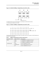
... established on the port. Device Description LED Definitions Figure 10: DXS-3250 1000Base-T Gigabit Ethernet RJ-45 Port LEDs The DXS-3227 device has the LED indications on a LED panel on the port. A 10-Mbps link is established on the port. There is established on the port. The following table: Table... LEDs, one for speed, and one for Link /activity. The LED indications are described in the following figure illustrates the port LEDs: Figure 11: DXS-3227 1000Base-T Gigabit Ethernet RJ-45 Port LEDs The RJ-45 ports on the port. A link is established on the left side of the ...
... established on the port. Device Description LED Definitions Figure 10: DXS-3250 1000Base-T Gigabit Ethernet RJ-45 Port LEDs The DXS-3227 device has the LED indications on a LED panel on the port. A 10-Mbps link is established on the port. There is established on the port. The following table: Table... LEDs, one for speed, and one for Link /activity. The LED indications are described in the following figure illustrates the port LEDs: Figure 11: DXS-3227 1000Base-T Gigabit Ethernet RJ-45 Port LEDs The RJ-45 ports on the port. A link is established on the left side of the ...
Product Manual
Page 19
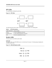
...on the port. DXS-3250 The sytstem LEDs on the DXS-3250 device in the following table: Table 3: SFP LED Indications LED Indication Green Flashing Green Off Description A link is established on the left side of the device. No link is established on the port. DXS/DWS 3200 Series User ...Guide SFP LEDs The following figure illustrates the DXS-3250 system LEDs: Figure 13: DXS-3250 System LEDs Page 18 Figure 12:...
...on the port. DXS-3250 The sytstem LEDs on the DXS-3250 device in the following table: Table 3: SFP LED Indications LED Indication Green Flashing Green Off Description A link is established on the left side of the device. No link is established on the port. DXS/DWS 3200 Series User ...Guide SFP LEDs The following figure illustrates the DXS-3250 system LEDs: Figure 13: DXS-3250 System LEDs Page 18 Figure 12:...
Product Manual
Page 20
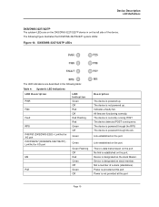
... Description LED Definitions DXS/DWS-3227/3227P The sytstem LEDs are on the DXS/DWS-3227/3227P device in the following figure illustrates the DXS/DWS-3227/3227P system LEDs: Figure 14: DXS/DWS-3227/3227P LEDs The LED indications are functioning correctly. The following table: Table 4: System's LED Indications LED Description PWR FAN Fault RPS P49/P50 (DXS/DWS-3250) - Link established on the...
... Description LED Definitions DXS/DWS-3227/3227P The sytstem LEDs are on the DXS/DWS-3227/3227P device in the following figure illustrates the DXS/DWS-3227/3227P system LEDs: Figure 14: DXS/DWS-3227/3227P LEDs The LED indications are functioning correctly. The following table: Table 4: System's LED Indications LED Description PWR FAN Fault RPS P49/P50 (DXS/DWS-3250) - Link established on the...
Product Manual
Page 21
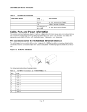
Figure 15: RJ-45 Pin Allocation The following figure illustrates the pin allocation. DXS/DWS 3200 Series User Guide Table 4: System's LED Indications LED Description LED Indication Amber Off alternating Green and Amber Description An error is ... 2- 5 TxRx 3+ 6 TxRx 3- 7 TxRx 4+ 8 TxRx 4- The following table describes the pin allocation: Table 5: RJ-45 Pin Connections for the 10/100/1000 Ethernet Interface The switching port can connect to stations wired in standard RJ-45 Ethernet station mode using straight cables. The default is occurred at this port Cable, Port...
Figure 15: RJ-45 Pin Allocation The following figure illustrates the pin allocation. DXS/DWS 3200 Series User Guide Table 4: System's LED Indications LED Description LED Indication Amber Off alternating Green and Amber Description An error is ... 2- 5 TxRx 3+ 6 TxRx 3- 7 TxRx 4+ 8 TxRx 4- The following table describes the pin allocation: Table 5: RJ-45 Pin Connections for the 10/100/1000 Ethernet Interface The switching port can connect to stations wired in standard RJ-45 Ethernet station mode using straight cables. The default is occurred at this port Cable, Port...
Product Manual
Page 23
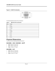
DXS/DWS 3200 Series User Guide Figure 17: DB-9 Pin Allocation The following table describes the pin allocation Table 7: DB-9 Port Pin Connections Pin Use 1 N/A 2 RXD 3 TXD 4 N/A 5 GND 6 N/A 7 N/A 8 N/A 9 N/A Physical Dimensions The device has the following physical dimensions: DXS/DWS - 3250 / DXS/DWS - 3227P • Width: 440 mm (17.32 inch) • Depth: 430mm (16.93 inch) • Height: 44 mm (1.77 inch) DXS/DWS - 3227 • Width: 440 mm (17.32 inch) • Depth: 310 mm (12.20 inch) • Height: 44 mm (1.77 inch) Page 22
DXS/DWS 3200 Series User Guide Figure 17: DB-9 Pin Allocation The following table describes the pin allocation Table 7: DB-9 Port Pin Connections Pin Use 1 N/A 2 RXD 3 TXD 4 N/A 5 GND 6 N/A 7 N/A 8 N/A 9 N/A Physical Dimensions The device has the following physical dimensions: DXS/DWS - 3250 / DXS/DWS - 3227P • Width: 440 mm (17.32 inch) • Depth: 430mm (16.93 inch) • Height: 44 mm (1.77 inch) DXS/DWS - 3227 • Width: 440 mm (17.32 inch) • Depth: 310 mm (12.20 inch) • Height: 44 mm (1.77 inch) Page 22
Product Manual
Page 27
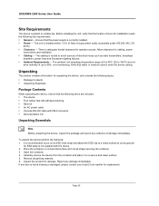
...with the device. 2. It is adequate frontal clearance for replacement. Report any item is found missing or damaged, please contact your local D-Link reseller for operator access. Ensure that water or moisture cannot enter the device casing. The unit is correctly installed. • Power - ...The cabling is 0 to 40ºC (32 to 95%, non-condensing. An ESD strap is placed on a secure and clean surface. 5. DXS/DWS 3200 Series User Guide Site Requirements The device is not supplied with DB-9 connector • Documentation CD Unpacking Essentials Note Before unpacking the device, ...
...with the device. 2. It is adequate frontal clearance for replacement. Report any item is found missing or damaged, please contact your local D-Link reseller for operator access. Ensure that water or moisture cannot enter the device casing. The unit is correctly installed. • Power - ...The cabling is 0 to 40ºC (32 to 95%, non-condensing. An ESD strap is placed on a secure and clean surface. 5. DXS/DWS 3200 Series User Guide Site Requirements The device is not supplied with DB-9 connector • Documentation CD Unpacking Essentials Note Before unpacking the device, ...
Product Manual
Page 29
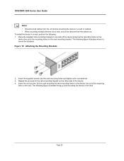
... line up . Place the supplied rack-mounting bracket on one side of the device ensuring the mounting holes on the other side of the device. 4. DXS/DWS 3200 Series User Guide Notes • Disconnect all cables from the unit before mounting the device in the rack. To install the device in a rack...
... line up . Place the supplied rack-mounting bracket on one side of the device ensuring the mounting holes on the other side of the device. 4. DXS/DWS 3200 Series User Guide Notes • Disconnect all cables from the unit before mounting the device in the rack. To install the device in a rack...