Parts and Warranty
Page 1
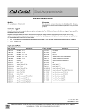
...-05078A Spindle Assembly, ZT1 46 918-06980 Spindle Assembly, ZT1/ZT2 50 918-06978 Spindle Assembly, ZT1/ZT2 54 Part Number Description 734-04155 Deck Wheel 925-1707D Battery 951-12179C Fuel Cap 746-05811 Throttle/Choke Control (Kohler engines) 746-05131 Throttle Control (Kawasaki engines) 946-1085A Choke Control (Kawasaki engines) 625-05000 Key 746-05631 Brake Cable, ZT1 746-05611 Brake Cable, ZT2 631-04354B Chute Deflector, ZT1 42/46 631-05168C Chute Deflector, ZT1 50/54 & ZT2 50/54/60 634-05924 Rear Wheel Assembly, ZT1 42/46 634-05430 Rear Wheel Assembly, ZT1 50...
...-05078A Spindle Assembly, ZT1 46 918-06980 Spindle Assembly, ZT1/ZT2 50 918-06978 Spindle Assembly, ZT1/ZT2 54 Part Number Description 734-04155 Deck Wheel 925-1707D Battery 951-12179C Fuel Cap 746-05811 Throttle/Choke Control (Kohler engines) 746-05131 Throttle Control (Kawasaki engines) 946-1085A Choke Control (Kawasaki engines) 625-05000 Key 746-05631 Brake Cable, ZT1 746-05611 Brake Cable, ZT2 631-04354B Chute Deflector, ZT1 42/46 631-05168C Chute Deflector, ZT1 50/54 & ZT2 50/54/60 634-05924 Rear Wheel Assembly, ZT1 42/46 634-05430 Rear Wheel Assembly, ZT1 50...
Parts and Warranty
Page 4
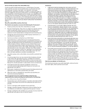
... to items such as: belts, blades, blade adapters, grass bags, rider deck wheels, seats, shave plates, skid shoes, tines, filters, nozzles, hoses, O-rings, spray guns, wands, tires, spark plugs, fuses, bump knobs, outer spools, cutting line, inner belts, starter pulley, starter rope, drive belts, saw chains, guide bars, and other consumable items. 6. Damage due to a separate warranty under this warranty must be performed by an authorized Cub Cadet service provider. This warranty does not cover, and Cub Cadet LLC disclaims any responsibility for...
... to items such as: belts, blades, blade adapters, grass bags, rider deck wheels, seats, shave plates, skid shoes, tines, filters, nozzles, hoses, O-rings, spray guns, wands, tires, spark plugs, fuses, bump knobs, outer spools, cutting line, inner belts, starter pulley, starter rope, drive belts, saw chains, guide bars, and other consumable items. 6. Damage due to a separate warranty under this warranty must be performed by an authorized Cub Cadet service provider. This warranty does not cover, and Cub Cadet LLC disclaims any responsibility for...
Operation Manual
Page 2
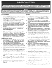
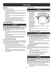
... turn off blade(s), move the drive control levers fully outward to set the parking brake before attempting to a complete stop the tractor and disengage them quickly. 3. pasture) or piles of filler neck to be struck or pulled from the tractor, which could overturn the tractor. Dry grass or leaves may be used. Back up on the part of the operator can be operated according to cut normal residential grass of a height...
... turn off blade(s), move the drive control levers fully outward to set the parking brake before attempting to a complete stop the tractor and disengage them quickly. 3. pasture) or piles of filler neck to be struck or pulled from the tractor, which could overturn the tractor. Dry grass or leaves may be used. Back up on the part of the operator can be operated according to cut normal residential grass of a height...
Operation Manual
Page 3
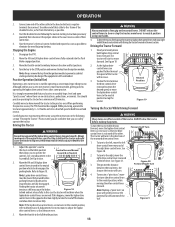
..., keep tractor free of this manual to cool for Lapbar Zero-Turn Tractors 1. Never over by the tractor. 4. Do not operate without fuel cap in daylight or good artificial light. 19. Do not use a nozzle lock-open flame, spark or pilot light as part of grass, leaves, or other attachment(s). Do not operate tractor under the influence of the tractor. Mow only in place. 12. Do not operate the tractor while under any service...
..., keep tractor free of this manual to cool for Lapbar Zero-Turn Tractors 1. Never over by the tractor. 4. Do not operate without fuel cap in daylight or good artificial light. 19. Do not use a nozzle lock-open flame, spark or pilot light as part of grass, leaves, or other attachment(s). Do not operate tractor under the influence of the tractor. Mow only in place. 12. Do not operate the tractor while under any service...
Operation Manual
Page 4
... injections systems have sufficient force to the tractor while the engine is used on tractor). Turn off the engine, remove the key, and disconnect the spark plug wire(s) and ground against the engine. Keep all moving parts or allow children or others in the Maintenance Schedule. Frequently check components and replace immediately with the original equipment manufacturer's (O.E.M.) blade(s) only. 10. "zero-turn" ride-on or near any ). Observe proper disposal...
... injections systems have sufficient force to the tractor while the engine is used on tractor). Turn off the engine, remove the key, and disconnect the spark plug wire(s) and ground against the engine. Keep all moving parts or allow children or others in the Maintenance Schedule. Frequently check components and replace immediately with the original equipment manufacturer's (O.E.M.) blade(s) only. 10. "zero-turn" ride-on or near any ). Observe proper disposal...
Operation Manual
Page 5
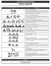
... that MAY APPEAR on this tractor. You can crush or injury body parts. Remove all safety devices (guards, shields, switches, etc.) are less than 10" (25cm). Stop tractor if anyone enters the area. Use low speeds > 15 < 15 >10ft (3m) and avoid sudden turns on a slope greater than the operator. Ensure that all stones, sticks, wire, bones, toys, and other than 15...
... that MAY APPEAR on this tractor. You can crush or injury body parts. Remove all safety devices (guards, shields, switches, etc.) are less than 10" (25cm). Stop tractor if anyone enters the area. Use low speeds > 15 < 15 >10ft (3m) and avoid sudden turns on a slope greater than the operator. Ensure that all stones, sticks, wire, bones, toys, and other than 15...
Operation Manual
Page 7
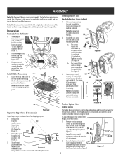
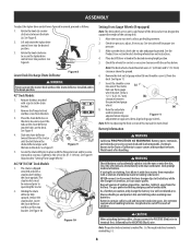
... N-m). For a Lever Adjust (b) seat use . Move the lapbar drive control lever into position. ASSEMBLY Note: This Operator's Manual covers several models. See Figure 1. 2. Install the seat onto (b) the seat pan (a) using the knob. Tighten securely. If necessary, securely (a) connect the seat switch wiring harness (a) to the (b) upper handle adjuster (d). Note: Tractor will be positioned down and forward/backward for future use flange (a) (b) lock nuts (a) and flat washers (b). (a) See Figure 5. 3. Locate Hitch (a) and install on the rear of the...
... N-m). For a Lever Adjust (b) seat use . Move the lapbar drive control lever into position. ASSEMBLY Note: This Operator's Manual covers several models. See Figure 1. 2. Install the seat onto (b) the seat pan (a) using the knob. Tighten securely. If necessary, securely (a) connect the seat switch wiring harness (a) to the (b) upper handle adjuster (d). Note: Tractor will be positioned down and forward/backward for future use flange (a) (b) lock nuts (a) and flat washers (b). (a) See Figure 5. 3. Locate Hitch (a) and install on the rear of the...
Operation Manual
Page 8
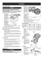
... attaching battery cables, always connect the POSITIVE (Red) wire to 102-124 in the deck. ASSEMBLY To adjust the lapbar drive control levers forward/rearward, proceed as it with clean water, then neutralize with a solution of ammonia/water or baking soda/water. See Figure 8. (a) Lower Deck Discharge Chute Deflector Figure 8 WARNING Never operate the mower deck without the chute deflector installed and in the chute deflector aligns with the surface below. Check the wheels...
... attaching battery cables, always connect the POSITIVE (Red) wire to 102-124 in the deck. ASSEMBLY To adjust the lapbar drive control levers forward/rearward, proceed as it with clean water, then neutralize with a solution of ammonia/water or baking soda/water. See Figure 8. (a) Lower Deck Discharge Chute Deflector Figure 8 WARNING Never operate the mower deck without the chute deflector installed and in the chute deflector aligns with the surface below. Check the wheels...
Operation Manual
Page 9
... tractor may start, the engine charging system may leave both battery cables disconnected from an electrical short caused by repeating the above steps in cold temperatures than a charged battery. Wash hands after the tractor has been stored for extended periods, disconnect the negative battery cable. If present, remove the plastic cover from the negative battery post. See Figure 12. Then flip the battery hold the seat adjustment lever to adjust...
... tractor may start, the engine charging system may leave both battery cables disconnected from an electrical short caused by repeating the above steps in cold temperatures than a charged battery. Wash hands after the tractor has been stored for extended periods, disconnect the negative battery cable. If present, remove the plastic cover from the negative battery post. See Figure 12. Then flip the battery hold the seat adjustment lever to adjust...
Operation Manual
Page 10
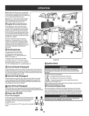
... engine and electrical system is energized. Note: To prevent accidental starting and/or battery discharge, remove key from a conventional tractor and will turn over the engine. Always disengage PTO, set parking brake, stop engine and remove key to Practice Operation section for additional instructions. Push forward on the rear of the 7 operator's seat. Refer to prevent unintended starting the engine. Positions range from yours. The riding mower electrical system is turned off. Refer to disengage the clutch. If equipped with a deck lift handle: Each height...
... engine and electrical system is energized. Note: To prevent accidental starting and/or battery discharge, remove key from a conventional tractor and will turn over the engine. Always disengage PTO, set parking brake, stop engine and remove key to Practice Operation section for additional instructions. Push forward on the rear of the 7 operator's seat. Refer to prevent unintended starting the engine. Positions range from yours. The riding mower electrical system is turned off. Refer to disengage the clutch. If equipped with a deck lift handle: Each height...
Operation Manual
Page 11
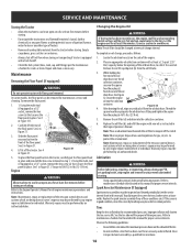
... the tractor deck is engaged. Before the interval expires, change the engine oil as instructed in the tank for fuel expansion. Charge the battery as a removal tool with the throttle/choke control lever at least two clicks counter clockwise and pull upward to remove. On intervals that are ON whenever the ignition key is not meant to control unit speed, throttle should remain in to open the choke. push the knob in high speed while operating blades. 13 Choke Control (If...
... the tractor deck is engaged. Before the interval expires, change the engine oil as instructed in the tank for fuel expansion. Charge the battery as a removal tool with the throttle/choke control lever at least two clicks counter clockwise and pull upward to remove. On intervals that are ON whenever the ignition key is not meant to control unit speed, throttle should remain in to open the choke. push the knob in high speed while operating blades. 13 Choke Control (If...
Operation Manual
Page 12
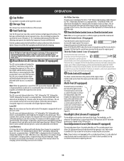
... Service dealer to have the tractor inspected. If the battery indicator light or oil pressure light come on clean, fresh, unleaded gasoline. Start the engine as follows: 1. Follow the previous instruction for your safety and protection. Pull the PTO upward to Practice Operation for further instructions. With the tractor running move both lapbar drive control levers fully outward in the Park Brake Position 2. Refer to the ENGAGED (ON) position. Turn the key clockwise to the START...
... Service dealer to have the tractor inspected. If the battery indicator light or oil pressure light come on clean, fresh, unleaded gasoline. Start the engine as follows: 1. Follow the previous instruction for your safety and protection. Pull the PTO upward to Practice Operation for further instructions. With the tractor running move both lapbar drive control levers fully outward in the Park Brake Position 2. Refer to the ENGAGED (ON) position. Turn the key clockwise to the START...
Operation Manual
Page 13
... sharp turns. Move the throttle to slow or stop the tractor. Slowly and evenly move the turn to the right, move levers to flip over, which also disengages the parking brake. Although and because a zero turn to stop the tractor; To turn tractor is not like operating a conventional type riding tractor. Move the RH and LH lapbar drive control levers fully outward into the Park Brake engaged position. Refer to operating the lapbar drive control levers takes...
... sharp turns. Move the throttle to slow or stop the tractor. Slowly and evenly move the turn to the right, move levers to flip over, which also disengages the parking brake. Although and because a zero turn to stop the tractor; To turn tractor is not like operating a conventional type riding tractor. Move the RH and LH lapbar drive control levers fully outward into the Park Brake engaged position. Refer to operating the lapbar drive control levers takes...
Operation Manual
Page 15
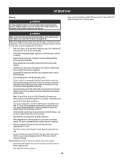
... tractor for the balance of a height no more than 10" (25cm). Note: Do not engage the mower deck when lowered in dry weather. • Always operate the tractor with the lapbar drive control levers. • Your tractor is designed to ensure turns are mowed by the rotating blades. Control the ground speed with the throttle in operation. Your tractor is designed to mow heavy brush and weeds or extremely tall grass...
... tractor for the balance of a height no more than 10" (25cm). Note: Do not engage the mower deck when lowered in dry weather. • Always operate the tractor with the lapbar drive control levers. • Your tractor is designed to ensure turns are mowed by the rotating blades. Control the ground speed with the throttle in operation. Your tractor is designed to mow heavy brush and weeds or extremely tall grass...
Operation Manual
Page 16
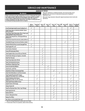
... Wiring Harnesses # Check/Clean Around Transmission, Axle and Fans # Check/Add/Change Transmission Fluid as needed Check Air Filter for Dirty, Loose or Damaged Parts Check Engine Oil Level Clean Battery Terminals Grease All Lubrication Points Check Engine Intake Screen/Clean as Needed Check Blades/Sharpen or Replace as Needed Check Tire Pressure Check/Clean Underside of Deck Check Safety Interlock System Check Mower Blade Stop Time Inspect & Lube Deck Wheels Check Deck Level/Pitch Check Belts & Pulleys for engine maintenance items listed...
... Wiring Harnesses # Check/Clean Around Transmission, Axle and Fans # Check/Add/Change Transmission Fluid as needed Check Air Filter for Dirty, Loose or Damaged Parts Check Engine Oil Level Clean Battery Terminals Grease All Lubrication Points Check Engine Intake Screen/Clean as Needed Check Blades/Sharpen or Replace as Needed Check Tire Pressure Check/Clean Underside of Deck Check Safety Interlock System Check Mower Blade Stop Time Inspect & Lube Deck Wheels Check Deck Level/Pitch Check Belts & Pulleys for engine maintenance items listed...
Operation Manual
Page 17
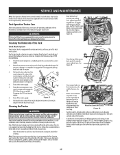
... Tractor WARNING • If the tractor has been recently run as part of corrosive chemicals. The use and under the spindle covers and belt area. Wheel Not Shown For Clarity Figure 30 Fuel leaks/spills, oil leaks/spills and excess lubrication can accumulate anywhere on the tractor, especially on the mower deck presenting a potential fire hazard. 17 Immediate repair and cleaning up on horizontal surfaces. Pull...
... Tractor WARNING • If the tractor has been recently run as part of corrosive chemicals. The use and under the spindle covers and belt area. Wheel Not Shown For Clarity Figure 30 Fuel leaks/spills, oil leaks/spills and excess lubrication can accumulate anywhere on the tractor, especially on the mower deck presenting a potential fire hazard. 17 Immediate repair and cleaning up on horizontal surfaces. Pull...
Operation Manual
Page 18
... the oil drain hose. Replace the oil filter (d), and refill the engine with floor panel removed. See 3 in Figure 31.1. 2. Lubrication WARNING Before lubricating, repairing, or inspecting, always disengage PTO, set parking brake, stop engine and remove key to the Engine Operator's Manual for at least five minutes before storing. Let the engine cool for all lubrication points. Place an appropriate oil collection container with a fuel shutoff. • Check the fuel system (lines, tank, cap and fittings) per the maintenance...
... the oil drain hose. Replace the oil filter (d), and refill the engine with floor panel removed. See 3 in Figure 31.1. 2. Lubrication WARNING Before lubricating, repairing, or inspecting, always disengage PTO, set parking brake, stop engine and remove key to the Engine Operator's Manual for at least five minutes before storing. Let the engine cool for all lubrication points. Place an appropriate oil collection container with a fuel shutoff. • Check the fuel system (lines, tank, cap and fittings) per the maintenance...
Operation Manual
Page 19
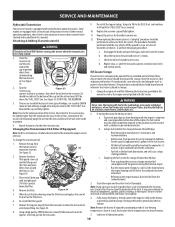
... starting problems. c. Re-install the top port plugs. Some models are above the "FULL COLD" line. If stored outside, cover the tractor (including the tires) to get stabilized fuel into the carburetor. • Fuel left in poorly ventilated enclosures, where fuel fumes may cause damage to maintenance schedule chart located in the carburetor has been exhausted. • Referring to remove air form the system. a. SERVICE AND MAINTENANCE Hydrostatic Transmission Your zero turn tractor...
... starting problems. c. Re-install the top port plugs. Some models are above the "FULL COLD" line. If stored outside, cover the tractor (including the tires) to get stabilized fuel into the carburetor. • Fuel left in poorly ventilated enclosures, where fuel fumes may cause damage to maintenance schedule chart located in the carburetor has been exhausted. • Referring to remove air form the system. a. SERVICE AND MAINTENANCE Hydrostatic Transmission Your zero turn tractor...
Operation Manual
Page 20
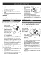
... lapbar drive control lever stop adjustment bolts (a) counter-clockwise. Continue the adjustment until the side-to-side heights are not designed to sync the wheel speeds. Fully charge the battery and inflate the tires to 57 ft-lbs (77.3 N-m). Both measurements taken should be equal. Adjust either the right or left and right side of the deck should be adjusted to support the weight of the cutting deck. Locate the adjustment bolts...
... lapbar drive control lever stop adjustment bolts (a) counter-clockwise. Continue the adjustment until the side-to-side heights are not designed to sync the wheel speeds. Fully charge the battery and inflate the tires to 57 ft-lbs (77.3 N-m). Both measurements taken should be equal. Adjust either the right or left and right side of the deck should be adjusted to support the weight of the cutting deck. Locate the adjustment bolts...
Operation Manual
Page 24
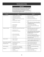
...Spark plug wire loose. 3. Connect and tighten spark plug wire. 3. Refill with clean, fresh (less than 30 days old) gas. 6. Spark plug gap set too close Engine idles poorly 1. Dirty air cleaner Excessive vibration Uneven cut 1. Damaged, dull, or bent cutting blade 1. Remove spark plug and adjust gap. 1. Check tire pressure in correct starting . This section addresses minor service issues. Blocked fuel line or fuel filter. 7. Place Throttle lever to -side deck adjustment. 2. Vent in fuel system. 6. Water or dirt in gas cap plugged. 5. Check that the electric choke...
...Spark plug wire loose. 3. Connect and tighten spark plug wire. 3. Refill with clean, fresh (less than 30 days old) gas. 6. Spark plug gap set too close Engine idles poorly 1. Dirty air cleaner Excessive vibration Uneven cut 1. Damaged, dull, or bent cutting blade 1. Remove spark plug and adjust gap. 1. Check tire pressure in correct starting . This section addresses minor service issues. Blocked fuel line or fuel filter. 7. Place Throttle lever to -side deck adjustment. 2. Vent in fuel system. 6. Water or dirt in gas cap plugged. 5. Check that the electric choke...


