
Series 1000 Brochure
Page 1
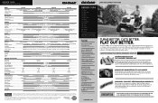
...limited warranties, see your fingertips from the only tractor in U.S.A. 12/12 © 2013 Cub Cadet Lawn and garden tractors SERIES 1000 LTX 1040 LTX 1042 KW LTX 1045 LTX 1046 LTX 1046 KW LTX 1050 LTX 1050 KW LGT 1050 LGT 1054 LGTX 1050 LGTX 1054 GTX 1054 Designed for long life ... the safety and use . The addition of the Cub Cadet Signature cut™ Aerospace engineers developed an advanced cutting system with dual steel wheel drive hubs 18" CHASSIS Chassis Type Frame Hood & Grill Fender & Bumper Robotically welded frame assembly Heavy-duty 9-gauge steel frame rails - 5-year ...
...limited warranties, see your fingertips from the only tractor in U.S.A. 12/12 © 2013 Cub Cadet Lawn and garden tractors SERIES 1000 LTX 1040 LTX 1042 KW LTX 1045 LTX 1046 LTX 1046 KW LTX 1050 LTX 1050 KW LGT 1050 LGT 1054 LGTX 1050 LGTX 1054 GTX 1054 Designed for long life ... the safety and use . The addition of the Cub Cadet Signature cut™ Aerospace engineers developed an advanced cutting system with dual steel wheel drive hubs 18" CHASSIS Chassis Type Frame Hood & Grill Fender & Bumper Robotically welded frame assembly Heavy-duty 9-gauge steel frame rails - 5-year ...
Series 1000 Brochure
Page 2
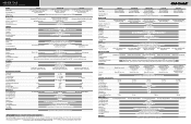
...Pulleys Deck Attach/Removal Deck Wash WARRANTY† LTX 1040 LTX 1042 KW LTX 1045 19 HP* Cub Cadet® professional-grade Kohler® single-cylinder OHV 18 HP* Cub Cadet® professional-grade Kawasaki® V-Twin OHV 20 HP* Cub Cadet® professional-grade Kohler® single-cylinder...iron w/dual grease fittings - 5-year limited warranty 3/4" 2 automotive-style 3/4" diameter with dual steel drive hubs 12" Robotically welded frame assembly Heavy-duty 9-gauge steel frame rails - 5-year limited warranty Corrosion- regulated 12V/H.D. 230 cold crank amp. 12V/H.D. 230 cold crank ...
...Pulleys Deck Attach/Removal Deck Wash WARRANTY† LTX 1040 LTX 1042 KW LTX 1045 19 HP* Cub Cadet® professional-grade Kohler® single-cylinder OHV 18 HP* Cub Cadet® professional-grade Kawasaki® V-Twin OHV 20 HP* Cub Cadet® professional-grade Kohler® single-cylinder...iron w/dual grease fittings - 5-year limited warranty 3/4" 2 automotive-style 3/4" diameter with dual steel drive hubs 12" Robotically welded frame assembly Heavy-duty 9-gauge steel frame rails - 5-year limited warranty Corrosion- regulated 12V/H.D. 230 cold crank amp. 12V/H.D. 230 cold crank ...
LTX 1040 Operator's Manual
Page 2
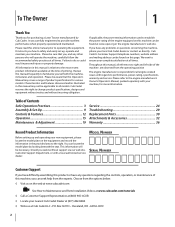
... contact us at the time of product specifications for various models. Model Number Serial Number Customer Support If you have difficulty assembling this machine can locate the model plate by Cub Cadet. It instructs you how to safely and easily set up and operating your machine, for more information. Failure to change product...
... contact us at the time of product specifications for various models. Model Number Serial Number Customer Support If you have difficulty assembling this machine can locate the model plate by Cub Cadet. It instructs you how to safely and easily set up and operating your machine, for more information. Failure to change product...
LTX 1040 Operator's Manual
Page 3
... of the mower and attachment discharge direction from the machine while it at least 75 feet 10. As with the blade(s) can cause serious personal assemble and operate. avoid discharging material against a wall or obstruction Know how to stop the machine and disengage them which ricochet can be used. Thrown objects...
... of the mower and attachment discharge direction from the machine while it at least 75 feet 10. As with the blade(s) can cause serious personal assemble and operate. avoid discharging material against a wall or obstruction Know how to stop the machine and disengage them which ricochet can be used. Thrown objects...

LTX 1040 Operator's Manual
Page 7
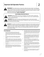
...may pick up and throw and objects which can amputate hands and feet. DANGER - Allow engine and muffler to cool before attempting to assemble and operate. WARNING- ROTATING BLADES Do not put hands or feet near rotating parts or under the cutting deck. Read, understand, ...accident. Never carry children, even with the blade(s) can cause serious personal injury. ROTATING BLADES Always look down and behind before attempting to assemble and operate DANGER- Contact with the blades off. BYSTANDERS Keep bystanders, helpers, children and pets at least 75 feet from the machine ...
...may pick up and throw and objects which can amputate hands and feet. DANGER - Allow engine and muffler to cool before attempting to assemble and operate. WARNING- ROTATING BLADES Do not put hands or feet near rotating parts or under the cutting deck. Read, understand, ...accident. Never carry children, even with the blade(s) can cause serious personal injury. ROTATING BLADES Always look down and behind before attempting to assemble and operate DANGER- Contact with the blades off. BYSTANDERS Keep bystanders, helpers, children and pets at least 75 feet from the machine ...
LTX 1040 Operator's Manual
Page 9
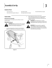
... between your lawn tractor. While holding the discharge chute with your left hand, remove the shipping brace with your right hand by grasping it clockwise. Assembly & Set-Up 3 Contents of the cutting deck.
... between your lawn tractor. While holding the discharge chute with your left hand, remove the shipping brace with your right hand by grasping it clockwise. Assembly & Set-Up 3 Contents of the cutting deck.
LTX 1040 Operator's Manual
Page 10
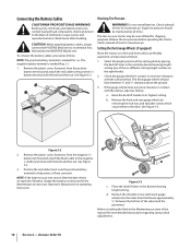
... rear gauge wheels by removing the lock nuts and shoulder screws which secure them to the positive (+) battery terminal with the bolt and hex nut. Assembly & Set-Up Battery posts, terminals, and related accessories contain lead and lead compounds, chemicals known to the State of this manual for more detailed instructions...
... rear gauge wheels by removing the lock nuts and shoulder screws which secure them to the positive (+) battery terminal with the bolt and hex nut. Assembly & Set-Up Battery posts, terminals, and related accessories contain lead and lead compounds, chemicals known to the State of this manual for more detailed instructions...

LTX 1040 Operator's Manual
Page 11
... ignition. This ensures that a proper expansion volume is shipped with oil in the seat-stop. Section 2 - Slide the seat forward or rearward to your engine. Assembly & Set-Up 11 Remove the fuel cap by turning it clicks into position before operating. then release the adjustment lever. Figure 3-5 WARNING! Add oil as...
... ignition. This ensures that a proper expansion volume is shipped with oil in the seat-stop. Section 2 - Slide the seat forward or rearward to your engine. Assembly & Set-Up 11 Remove the fuel cap by turning it clicks into position before operating. then release the adjustment lever. Figure 3-5 WARNING! Add oil as...
LTX 1040 Operator's Manual
Page 12
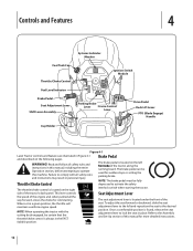
...the running board. Once a comfortable position is located on the left and reposition the seat to the desired position. Refer to the Assembly and Set-Up section of the seat. When set in place. NOTE: When operating the tractor with all the way forward, closes...Features 4 Fuel Tank Cap Systems Indicator Monitor Throttle/Choke Control Ignition Switch Module Fuel Level Indicator Brake Pedal Seat Adjustment Lever Shift Lever Assembly Parking Brake Lever Cruise Control Lever Drive Pedal Deck Lift Lever PTO (Blade Engage) Handle Cup Holder Figure 4-1 Lawn Tractor controls and...
...the running board. Once a comfortable position is located on the left and reposition the seat to the desired position. Refer to the Assembly and Set-Up section of the seat. When set in place. NOTE: When operating the tractor with all the way forward, closes...Features 4 Fuel Tank Cap Systems Indicator Monitor Throttle/Choke Control Ignition Switch Module Fuel Level Indicator Brake Pedal Seat Adjustment Lever Shift Lever Assembly Parking Brake Lever Cruise Control Lever Drive Pedal Deck Lift Lever PTO (Blade Engage) Handle Cup Holder Figure 4-1 Lawn Tractor controls and...
LTX 1040 Operator's Manual
Page 15
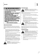
...operate the tractor if the interlock system is malfunctioning. After the engine starts, release the key. Doing so may cause damage to your Cub Cadet dealer. • The safety interlock system prevents the engine from the ignition switch to the NORMAL MOWING position. If you strike a ...ignition key clockwise to the STOP position. 4. CAUTION: Do NOT hold the key in a "rich" fuel mixture and cause the engine to the Assembly & Set-Up section of the operator. WARNING! READ OPERATOR'S MANUAL Safety Interlock Switches This tractor is moved into the engaged (ON) position with...
...operate the tractor if the interlock system is malfunctioning. After the engine starts, release the key. Doing so may cause damage to your Cub Cadet dealer. • The safety interlock system prevents the engine from the ignition switch to the NORMAL MOWING position. If you strike a ...ignition key clockwise to the STOP position. 4. CAUTION: Do NOT hold the key in a "rich" fuel mixture and cause the engine to the Assembly & Set-Up section of the operator. WARNING! READ OPERATOR'S MANUAL Safety Interlock Switches This tractor is moved into the engaged (ON) position with...
LTX 1040 Operator's Manual
Page 22
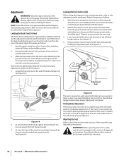
...pressure. The front of this manual for proper adjustment and proceed, if necessary. 1. Measure the distance from front to the Set-Up and Assembly section of the deck should be performed. Adjust if necessary as follows: 1. See Figure 6-5. Hex Bolt Adjustment Gear Figure 6-5 The deck...it clicks into place. 22 Section 6 - Adjustments WARNING! parking brake. Stand behind the machine and pull See Figure 6-4. Protect your Cub Cadet dealer to the ground and the distance from the front hanger bracket. To lower the front of the left deck hanger bracket when proper...
...pressure. The front of this manual for proper adjustment and proceed, if necessary. 1. Measure the distance from front to the Set-Up and Assembly section of the deck should be performed. Adjust if necessary as follows: 1. See Figure 6-5. Hex Bolt Adjustment Gear Figure 6-5 The deck...it clicks into place. 22 Section 6 - Adjustments WARNING! parking brake. Stand behind the machine and pull See Figure 6-4. Protect your Cub Cadet dealer to the ground and the distance from the front hanger bracket. To lower the front of the left deck hanger bracket when proper...
LTX 1040 Operator's Manual
Page 27
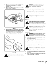
... and the cutting blade to act as instructed in the Operation section of connection. Jump Starting WARNING! Do not allow cable clamps to the spindle assembly. Make the final connection on a vehicle (i.e. Service 27 A poorly balanced blade will cause excessive vibration, may cause damage to install the blade with the side...
... and the cutting blade to act as instructed in the Operation section of connection. Jump Starting WARNING! Do not allow cable clamps to the spindle assembly. Make the final connection on a vehicle (i.e. Service 27 A poorly balanced blade will cause excessive vibration, may cause damage to install the blade with the side...
LTX 1040 Operator's Manual
Page 31
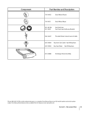
Component Part Number and Description 734-04155 Deck Wheel (Front) 734-0973 Deck Wheel (Rear) 951-12179A 951-10947 Fuel Tank Cap Fuel Tank Cap (California Models) 946-04617 Throttle/Choke Control Lever & Cable 625-05000 Key Asm-Cub Cadet Key W/Keychain 625-05002 Key Asm-Black Key W/Keychain 631-04288 Discharge Chute Assembly Phone (800) 965-4CUB to order replacement parts or a complete Parts Manual (have your full model number and serial number ready). Section 9 - Parts Manual downloads are also available free of charge at www.cubcadet.com. Replacement Parts 31
Component Part Number and Description 734-04155 Deck Wheel (Front) 734-0973 Deck Wheel (Rear) 951-12179A 951-10947 Fuel Tank Cap Fuel Tank Cap (California Models) 946-04617 Throttle/Choke Control Lever & Cable 625-05000 Key Asm-Cub Cadet Key W/Keychain 625-05002 Key Asm-Black Key W/Keychain 631-04288 Discharge Chute Assembly Phone (800) 965-4CUB to order replacement parts or a complete Parts Manual (have your full model number and serial number ready). Section 9 - Parts Manual downloads are also available free of charge at www.cubcadet.com. Replacement Parts 31
LTX 1040 Operator's Manual
Page 35
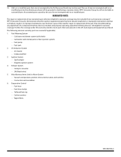
... • Spark plug(s) • Magneto ignition system 4. Miscellaneous Items Used in Above System • Vacuum, temperature, position, time sensitive valves and switches • Connectors and assemblies 6. The use of any adjustment of the part. The following emission warranty parts are not exempted by the Air Resources Board may be excluded from...
... • Spark plug(s) • Magneto ignition system 4. Miscellaneous Items Used in Above System • Vacuum, temperature, position, time sensitive valves and switches • Connectors and assemblies 6. The use of any adjustment of the part. The following emission warranty parts are not exempted by the Air Resources Board may be excluded from...
Parts Manual
Page 2
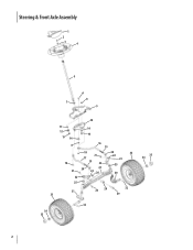
Steering & Front Axle Assembly 1 2 3 4 5 6 8 7 9 10 11 14 12 15 13 14 8 16 19 18 21 17 18 19 24 21 20 27 24 26 22 20 33 22 23 25 30 25 31 33 23 28 32 29 32 34 35 35 34 2
Steering & Front Axle Assembly 1 2 3 4 5 6 8 7 9 10 11 14 12 15 13 14 8 16 19 18 21 17 18 19 24 21 20 27 24 26 22 20 33 22 23 25 30 25 31 33 23 28 32 29 32 34 35 35 34 2

Parts Manual
Page 3
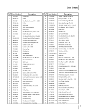
Steering & Front Axle Assembly Ref. Part Number Description 1 731-04532B Steering Wheel Cover 2 710-04484 Hex Washer Screw, 5⁄16-18 x .750 3 936-3004 Flat Washer, .406 x .875 x .105 4 ... x 1.5075 29 710-04824 Hex Screw, 1⁄2-13 x 2.5 30 638-04021-0637 RH Axle Assembly 31 638-04027-0637 LH Axle Assembly 32 714-0162 Cotter Pin, 5⁄32 x 1.25 33 N/A Wheel Assembly (Plastic Flange) - 634-04405-0499 Rim Assembly - 734-1731-0901 Tire - 734-0255 Tubeless Air Valve - 741-0990B Flange w/ Fitting Bearing...
Steering & Front Axle Assembly Ref. Part Number Description 1 731-04532B Steering Wheel Cover 2 710-04484 Hex Washer Screw, 5⁄16-18 x .750 3 936-3004 Flat Washer, .406 x .875 x .105 4 ... x 1.5075 29 710-04824 Hex Screw, 1⁄2-13 x 2.5 30 638-04021-0637 RH Axle Assembly 31 638-04027-0637 LH Axle Assembly 32 714-0162 Cotter Pin, 5⁄32 x 1.25 33 N/A Wheel Assembly (Plastic Flange) - 634-04405-0499 Rim Assembly - 734-1731-0901 Tire - 734-0255 Tubeless Air Valve - 741-0990B Flange w/ Fitting Bearing...

Parts Manual
Page 5
Hood & Dash Assembly Ref. Part Number 1 931-06634 2 731-06543 3 731-06542 4 931-04322 - 777X43335 - 777X43334 5 710-0895 6 936-3020 7 936-0222 8 931-06559 9 931-06558 10 925-...
Hood & Dash Assembly Ref. Part Number 1 931-06634 2 731-06543 3 731-06542 4 931-04322 - 777X43335 - 777X43334 5 710-0895 6 936-3020 7 936-0222 8 931-06559 9 931-06558 10 925-...

Parts Manual
Page 7
..., 1⁄4-20 x .500 45 716-0106A E-Type Ring 46 941-0225 47 746-0968 Hex Flange Bearing Lift Cable 48 683-04223-0637 Lift Shift Assembly 49 914-0104 Cotter Pin, .072 x 1.13 50 732-0874 Torsion Spring 51 747-04962A Lift Handle 52 720-0311 Handle Grip 53 736-0105...
..., 1⁄4-20 x .500 45 716-0106A E-Type Ring 46 941-0225 47 746-0968 Hex Flange Bearing Lift Cable 48 683-04223-0637 Lift Shift Assembly 49 914-0104 Cotter Pin, .072 x 1.13 50 732-0874 Torsion Spring 51 747-04962A Lift Handle 52 720-0311 Handle Grip 53 736-0105...
Parts Manual
Page 9
... Washer, 1.00 x .632 x .010 Shoulder Spacer, 1.00 x .38 x .38 Jam Nut, 7⁄16-20 Flat Idler Pulley Hex Screw, 3⁄8-16 x 2.25 Transmatic Drive Assembly Ref. Drive System Ref. Part Number Description 34 731-04604 Sleeve, .758 x .821 x 2.4375 35 712-04063 Flange Lock Nut, 5⁄16-18 36 732... 714-04040 Bow-Tie Cotter Pin 65 783-06278 Bracket Reinforcement Plate 66 711-05068 Clevis Pin, 5⁄16-3.985 67 647-04152 Brake Control Assembly 68 732-04587 Extension Spring, .63 x 4.95 69 710-0604A Hex Washer Screw, 5⁄16-18 x .625 70 783-05940 Pedal Strap Support ...
... Washer, 1.00 x .632 x .010 Shoulder Spacer, 1.00 x .38 x .38 Jam Nut, 7⁄16-20 Flat Idler Pulley Hex Screw, 3⁄8-16 x 2.25 Transmatic Drive Assembly Ref. Drive System Ref. Part Number Description 34 731-04604 Sleeve, .758 x .821 x 2.4375 35 712-04063 Flange Lock Nut, 5⁄16-18 36 732... 714-04040 Bow-Tie Cotter Pin 65 783-06278 Bracket Reinforcement Plate 66 711-05068 Clevis Pin, 5⁄16-3.985 67 647-04152 Brake Control Assembly 68 732-04587 Extension Spring, .63 x 4.95 69 710-0604A Hex Washer Screw, 5⁄16-18 x .625 70 783-05940 Pedal Strap Support ...
Parts Manual
Page 11
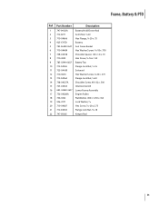
...-04064 Flange Lock Nut, 1⁄4-20 14 738-04237A Shoulder Screw, #10-32 x .500 15 725-04363 Interlock Switch 16 683-04469-0637 Lower Frame Assembly 17 756-04208A Engine Pulley 18 736-0322 Flat Washer, .450 x 1.250 x .164 19 936-0171 Lock Washer, 7⁄16 20 710-04607 Hex Screw...
...-04064 Flange Lock Nut, 1⁄4-20 14 738-04237A Shoulder Screw, #10-32 x .500 15 725-04363 Interlock Switch 16 683-04469-0637 Lower Frame Assembly 17 756-04208A Engine Pulley 18 736-0322 Flat Washer, .450 x 1.250 x .164 19 936-0171 Lock Washer, 7⁄16 20 710-04607 Hex Screw...


