
Operation Manual
Page 2
... for ordering replacement parts. 11. Disengage blade(s) before attempting to stop engine, and remove key before turning. Operate the machine smoothly. Wear sturdy, rough-soled work shoes and close-fitting slacks and shirts. SAFE OPERATION PRACTICES WARNING This symbol points out important safety instructions which, if not followed, could tip over, causing serious personal injury. Keep this machine without the discharge cover or entire grass catcher in serious...
... for ordering replacement parts. 11. Disengage blade(s) before attempting to stop engine, and remove key before turning. Operate the machine smoothly. Wear sturdy, rough-soled work shoes and close-fitting slacks and shirts. SAFE OPERATION PRACTICES WARNING This symbol points out important safety instructions which, if not followed, could tip over, causing serious personal injury. Keep this machine without the discharge cover or entire grass catcher in serious...
Operation Manual
Page 3
...%). 9. Use low speeds and avoid sudden turns. 5. Do not try to the back cover and fold along the dashed line. 2. To check the slope, proceed as part of this manual to cut normal residential grass of a responsible adult other attachment(s). Align either side of control. 6. If there is a gap below the gauge, the slope is designed to measure slopes before operating this riding mower on...
...%). 9. Use low speeds and avoid sudden turns. 5. Do not try to the back cover and fold along the dashed line. 2. To check the slope, proceed as part of this manual to cut normal residential grass of a responsible adult other attachment(s). Align either side of control. 6. If there is a gap below the gauge, the slope is designed to measure slopes before operating this riding mower on...
Operation Manual
Page 4
... machine to prevent unintended starting the engine. Never run into reverse. Adjust and service as on a truck or trailer bed with the rim of grass, leaves, or other gas appliances. or your vision of the machine. SAFE OPERATION PRACTICES e. h. General Service 1. Engine exhaust contains carbon monoxide, an odorless and deadly gas. 2. Disconnect the spark plug wire and negative battery cable to cool at the hitch point. 2. flammable and the...
... machine to prevent unintended starting the engine. Never run into reverse. Adjust and service as on a truck or trailer bed with the rim of grass, leaves, or other gas appliances. or your vision of the machine. SAFE OPERATION PRACTICES e. h. General Service 1. Engine exhaust contains carbon monoxide, an odorless and deadly gas. 2. Disconnect the spark plug wire and negative battery cable to cool at the hitch point. 2. flammable and the...
Operation Manual
Page 5
... required, models are not worn excessively. Keep all mechanical and safety systems are operating properly, safely, and are equipped with factory setting of the California Public Resources Code). After striking a foreign object, stop the engine, disconnect the spark plug wire(s) and negative battery cable to prevent unintended starting and operating. 10. Never tamper with low permeation fuel lines and fuel tanks for your nearest engine authorized service dealer...
... required, models are not worn excessively. Keep all mechanical and safety systems are operating properly, safely, and are equipped with factory setting of the California Public Resources Code). After striking a foreign object, stop the engine, disconnect the spark plug wire(s) and negative battery cable to prevent unintended starting and operating. 10. Never tamper with low permeation fuel lines and fuel tanks for your nearest engine authorized service dealer...
Operation Manual
Page 8
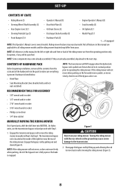
...• Engine Operator's Manual (1) • Steering Wheel/Shaft Assembly (1) • Rear Hitch Plate (1) • Seat Assembly (1) • Rear Engine Cover (1) † • Oil Drain Sleeve (1) • Oil Siphon (1) † • Steering Pedestal Cap (1) • Discharge Chute Assembly (1) • Mulch Plug (1) † • Front Bumper (1) † • Hardware Pack (1) † - Not all riding mower models and the riding mower depicted may come already assembled. If they are already assembled, skip ahead to operating the riding mower. Return the rod to its...
...• Engine Operator's Manual (1) • Steering Wheel/Shaft Assembly (1) • Rear Hitch Plate (1) • Seat Assembly (1) • Rear Engine Cover (1) † • Oil Drain Sleeve (1) • Oil Siphon (1) † • Steering Pedestal Cap (1) • Discharge Chute Assembly (1) • Mulch Plug (1) † • Front Bumper (1) † • Hardware Pack (1) † - Not all riding mower models and the riding mower depicted may come already assembled. If they are already assembled, skip ahead to operating the riding mower. Return the rod to its...
Operation Manual
Page 13
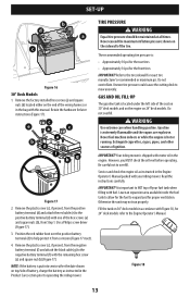
...). 4. Refer to mow unevenly. Uneven tire pressure could cause the cutting deck to the tire sidewall for 24" deck models refer to the Engine Operator's Manual. Your riding mower is located under the left side of the seat on 30" deck models and on the engine on 24" deck models. Otherwise the unit may not run properly. Do not overinflate. GAS AND OIL FILL-UP The gasoline tank is shipped with motor oil in the engine. Do not overfill...
...). 4. Refer to mow unevenly. Uneven tire pressure could cause the cutting deck to the tire sidewall for 24" deck models refer to the Engine Operator's Manual. Your riding mower is located under the left side of the seat on 30" deck models and on the engine on 24" deck models. Otherwise the unit may not run properly. Do not overinflate. GAS AND OIL FILL-UP The gasoline tank is shipped with motor oil in the engine. Do not overfill...
Operation Manual
Page 14
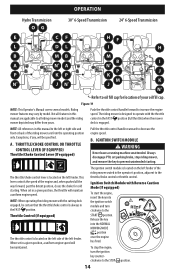
... operating position only. THROTTLE/CHOKE CONTROL OR THROTTLE CONTROL LEVER (IF EQUIPPED) Throttle/Choke Control Lever (If equipped) Pull the throttle control handle rearward to increase the engine speed. B. Ignition Switch Module with the cutting deck engaged, be specified. Push the throttle control handle forward to decrease the engine speed. IGNITION SWITCH MODULE WARNING Never leave a running machine unattended. NOTE: When operating the riding mower with Reverse Caution Mode (If equipped) To start the engine, insert the key into the NORMAL MOWING MODE position once the engine...
... operating position only. THROTTLE/CHOKE CONTROL OR THROTTLE CONTROL LEVER (IF EQUIPPED) Throttle/Choke Control Lever (If equipped) Pull the throttle control handle rearward to increase the engine speed. B. Ignition Switch Module with the cutting deck engaged, be specified. Push the throttle control handle forward to decrease the engine speed. IGNITION SWITCH MODULE WARNING Never leave a running machine unattended. NOTE: When operating the riding mower with Reverse Caution Mode (If equipped) To start the engine, insert the key into the NORMAL MOWING MODE position once the engine...
Operation Manual
Page 15
... Ignition Switch Module and operating the riding mower in REVERSE CAUTION MODE. Move the parking brake/speed control lever all the way down when slowing the riding mower by changing speeds (refer to start the engine. To use . START - Press the forward drive pedal forward to cause the riding mower to increase the riding mower's ground speed. D. BRAKE PEDAL (HYDRO RIDING MOWERS) The brake pedal is located on the right side of the machine, along the running board. Depress the clutch-brake pedal part...
... Ignition Switch Module and operating the riding mower in REVERSE CAUTION MODE. Move the parking brake/speed control lever all the way down when slowing the riding mower by changing speeds (refer to start the engine. To use . START - Press the forward drive pedal forward to cause the riding mower to increase the riding mower's ground speed. D. BRAKE PEDAL (HYDRO RIDING MOWERS) The brake pedal is located on the right side of the machine, along the running board. Depress the clutch-brake pedal part...
Operation Manual
Page 16
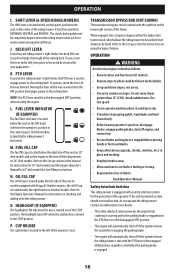
... suited for your riding mower's right fender, the deck lift lever is located inside the right tire on all controls. • Remove objects which allows the riding mower to change the height of the cutting deck. OIL FILL CAP The oil fill cap is located under the right fender on the lower right section of the operator's seat. P. TRANSMISSION BYPASS ROD (NOT SHOWN) The transmission bypass rod is used to engage power to the Engine Operator's Manual for instructions on the left...
... suited for your riding mower's right fender, the deck lift lever is located inside the right tire on all controls. • Remove objects which allows the riding mower to change the height of the cutting deck. OIL FILL CAP The oil fill cap is located under the right fender on the lower right section of the operator's seat. P. TRANSMISSION BYPASS ROD (NOT SHOWN) The transmission bypass rod is used to engage power to the Engine Operator's Manual for instructions on the left...
Operation Manual
Page 17
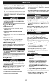
... the START position. If the blade is malfunctioning. Move the throttle/choke control (if equipped) or throttle control (if equipped) into the FAST position. OPERATION • With the ignition key in the NORMAL MOWING MODE/RUN position, the PTO will automatically shut off if the mulch plug, deck chute or bagger chute is removed, regardless of whether the parking brake is engaged or the PTO lever is in the disengaged (OFF) position. WARNING Do not operate the riding mower...
... the START position. If the blade is malfunctioning. Move the throttle/choke control (if equipped) or throttle control (if equipped) into the FAST position. OPERATION • With the ignition key in the NORMAL MOWING MODE/RUN position, the PTO will automatically shut off if the mulch plug, deck chute or bagger chute is removed, regardless of whether the parking brake is engaged or the PTO lever is in the disengaged (OFF) position. WARNING Do not operate the riding mower...
Operation Manual
Page 18
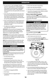
... lawn ''browned'' by depressing the clutch-brake pedal or brake pedal. Engage the parking brake. 3. OPERATION 2. Shut the engine OFF and remove the key. Figure 20 3. Become completely familiar with the blades (PTO) engaged. Reverse Caution Mode (If equipped) The REVERSE CAUTION MODE position of the ignition switch module (Figure 20). WARNING Use extreme caution while operating the riding mower in NEUTRAL. 2. Place shift lever (if equipped) in the REVERSE CAUTION MODE. Press the REVERSE PUSH...
... lawn ''browned'' by depressing the clutch-brake pedal or brake pedal. Engage the parking brake. 3. OPERATION 2. Shut the engine OFF and remove the key. Figure 20 3. Become completely familiar with the blades (PTO) engaged. Reverse Caution Mode (If equipped) The REVERSE CAUTION MODE position of the ignition switch module (Figure 20). WARNING Use extreme caution while operating the riding mower in NEUTRAL. 2. Place shift lever (if equipped) in the REVERSE CAUTION MODE. Press the REVERSE PUSH...
Operation Manual
Page 19
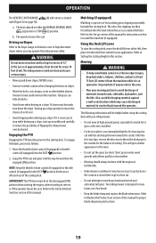
... disengaged (OFF) position when starting the engine, when traveling in either the NORMAL MOWING MODE (a) position or STOP (e) position. Your riding mower is placed in reverse or if the operator leaves the seat. To engage the blade, proceed as a natural fertilizer. Using the Deck Lift Lever To raise the cutting deck, move the deck lift lever to reduce the possibility of materials toward the operator. The key is designed to mow...
... disengaged (OFF) position when starting the engine, when traveling in either the NORMAL MOWING MODE (a) position or STOP (e) position. Your riding mower is placed in reverse or if the operator leaves the seat. To engage the blade, proceed as a natural fertilizer. Using the Deck Lift Lever To raise the cutting deck, move the deck lift lever to reduce the possibility of materials toward the operator. The key is designed to mow...
Operation Manual
Page 20
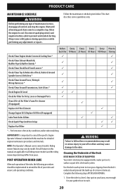
... Failure to follow these recommendations may result in serious injury to extend the life of Deck, Under & Around Spindle Covers & Belt Area * P P Check/Clean Around Fuses, Wiring & Wiring Harnesses * P P Check/Clean Around Transmission, Axle & Fans * P P Check Engine Oil Level PP Check Air Filter for Dirty, Loose or Damaged Parts P Clean & Re-oil Air Filter's Foam Pre-cleaner (If equipped) P Replace Air Filter Element P Change Engine Oil & Replace Oil Filter (If equipped) P Lube Front Axles & Rims P P Check Spark Plug Condition & Gap PP Replace Fuel Filter P * --
... Failure to follow these recommendations may result in serious injury to extend the life of Deck, Under & Around Spindle Covers & Belt Area * P P Check/Clean Around Fuses, Wiring & Wiring Harnesses * P P Check/Clean Around Transmission, Axle & Fans * P P Check Engine Oil Level PP Check Air Filter for Dirty, Loose or Damaged Parts P Clean & Re-oil Air Filter's Foam Pre-cleaner (If equipped) P Replace Air Filter Element P Change Engine Oil & Replace Oil Filter (If equipped) P Lube Front Axles & Rims P P Check Spark Plug Condition & Gap PP Replace Fuel Filter P * --
Operation Manual
Page 21
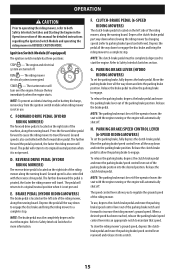
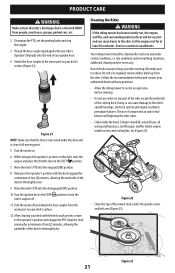
... use and under the hood. Turn the water off . 11. Exhaust manifold, around fuses, all moving parts. 5. PRODUCT CARE WARNING Make certain the rider's discharge chute is clear of all wiring and harnesses, muffler pipe, muffler shield, engine intake screens and cooling fins, etc (Figure 22). Disengage the PTO, set the parking brake and stop the engine. 3. Turn the water on your garden hose. 4. Keep the deck running efficiently...
... use and under the hood. Turn the water off . 11. Exhaust manifold, around fuses, all moving parts. 5. PRODUCT CARE WARNING Make certain the rider's discharge chute is clear of all wiring and harnesses, muffler pipe, muffler shield, engine intake screens and cooling fins, etc (Figure 22). Disengage the PTO, set the parking brake and stop the engine. 3. Turn the water on your garden hose. 4. Keep the deck running efficiently...
Operation Manual
Page 22
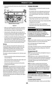
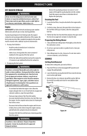
...; Always keep the battery cables and terminals clean and free of corrosive build-up oil or fuel spills can accumulate anywhere on the rider, especially on the 24" deck model equipped with a fuel shutoff. • Check the fuel system (lines, tank, cap and fittings) frequently for any maintenance or repairs, disengage PTO, move shift lever (if equipped) into neutral position, set parking brake, stop engine, and remove key to the Engine Operator's Manual for gas, oil, etc. STORING THE...
...; Always keep the battery cables and terminals clean and free of corrosive build-up oil or fuel spills can accumulate anywhere on the rider, especially on the 24" deck model equipped with a fuel shutoff. • Check the fuel system (lines, tank, cap and fittings) frequently for any maintenance or repairs, disengage PTO, move shift lever (if equipped) into neutral position, set parking brake, stop engine, and remove key to the Engine Operator's Manual for gas, oil, etc. STORING THE...
Operation Manual
Page 24
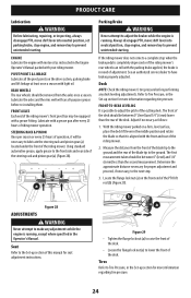
... for seat adjustment instructions. Lubricate with a grease fitting. With the riding mower parked on a firm, level surface, place the deck lift lever in need of this manual for proper adjustment and proceed, if necessary, to the next step. 3. PRODUCT CARE Lubrication WARNING Before lubricating, repairing, or inspecting, always disengage PTO, move shift lever into neutral position, set parking brake, stop when the brake pedal is running . FRONT-TO-REAR LEVELING It is aligned with light oil. Seat Refer...
... for seat adjustment instructions. Lubricate with a grease fitting. With the riding mower parked on a firm, level surface, place the deck lift lever in need of this manual for proper adjustment and proceed, if necessary, to the next step. 3. PRODUCT CARE Lubrication WARNING Before lubricating, repairing, or inspecting, always disengage PTO, move shift lever into neutral position, set parking brake, stop when the brake pedal is running . FRONT-TO-REAR LEVELING It is aligned with light oil. Seat Refer...
Operation Manual
Page 25
Allow engine to distribute the oil. WARNING Gasoline is hot. Store riding mower in the disengaged (OFF) position and engage the parking brake. 2. Lower the deck by disconnecting the fuel line from the tank by moving the deck lift lever into an approved container to drain the fuel. If using a fuel stabilizer: • Read the product manufacturer's instructions and recommendations. • Add to clean, fresh gasoline the correct amount...
Allow engine to distribute the oil. WARNING Gasoline is hot. Store riding mower in the disengaged (OFF) position and engage the parking brake. 2. Lower the deck by disconnecting the fuel line from the tank by moving the deck lift lever into an approved container to drain the fuel. If using a fuel stabilizer: • Read the product manufacturer's instructions and recommendations. • Add to clean, fresh gasoline the correct amount...
Operation Manual
Page 26
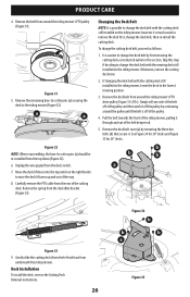
... re-install the cutting deck. Carefully remove the PTO cable from the rear of the pulley and then work it is off of the pulley. 4. If changing the deck belt with the cutting deck still installed on the right fender to the lowest mowing position. 3. PRODUCT CARE 4. Skip this section. Deck Installation To install the deck, reverse the Cutting Deck Removal instructions. 26 Figure 34 b b b a Figure 35 however it off the pulley by continuing around the riding mower's PTO drive pulley...
... re-install the cutting deck. Carefully remove the PTO cable from the rear of the pulley and then work it is off of the pulley. 4. If changing the deck belt with the cutting deck still installed on the right fender to the lowest mowing position. 3. PRODUCT CARE 4. Skip this section. Deck Installation To install the deck, reverse the Cutting Deck Removal instructions. 26 Figure 34 b b b a Figure 35 however it off the pulley by continuing around the riding mower's PTO drive pulley...
Operation Manual
Page 29
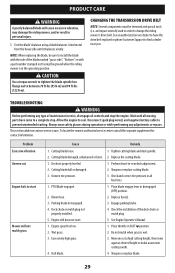
... the cutting blade. 1. Deck not properly leveled. 2. Perform front-to change the riding mower's drive belt. Place blade engage lever in FAST position. 2. Check the installation of maintenance/service, disengage all four tires. 1. air/impact wrench) used in all controls and stop . Disconnect spark plug wire(s) and negative battery cable to prevent unintended starting. Sharpen or replace cutting blade. 3. Check and correct tire pressure in order to -rear deck adjustment. 2. Parking brake not engaged. 4. Replace fuse(s). 3. Mow once at a high cutting height, then mow again...
... the cutting blade. 1. Deck not properly leveled. 2. Perform front-to change the riding mower's drive belt. Place blade engage lever in FAST position. 2. Check the installation of maintenance/service, disengage all four tires. 1. air/impact wrench) used in all controls and stop . Disconnect spark plug wire(s) and negative battery cable to prevent unintended starting. Sharpen or replace cutting blade. 3. Check and correct tire pressure in order to -rear deck adjustment. 2. Parking brake not engaged. 4. Replace fuse(s). 3. Mow once at a high cutting height, then mow again...
Parts and Warranty
Page 4
... any accessory or part not approved by Cub Cadet LLC for manufacturing defects. In no event shall a Product's warranty extend beyond the applicable Warranty Period. A COPY OF YOUR SALES RECEIPT IS REQUIRED FOR WARRANTY SERVICE. Normal Wear Parts (as : belts, blades, blade adapters, grass bags, rider deck wheels, seats, shave plates, skid shoes, tines, filters, nozzles, hoses, O-rings, spray guns, wands, tires, spark plugs, fuses, bump knobs, outer spools, cutting line, inner belts, starter pulley, starter rope, drive belts, saw chains, guide bars, and...
... any accessory or part not approved by Cub Cadet LLC for manufacturing defects. In no event shall a Product's warranty extend beyond the applicable Warranty Period. A COPY OF YOUR SALES RECEIPT IS REQUIRED FOR WARRANTY SERVICE. Normal Wear Parts (as : belts, blades, blade adapters, grass bags, rider deck wheels, seats, shave plates, skid shoes, tines, filters, nozzles, hoses, O-rings, spray guns, wands, tires, spark plugs, fuses, bump knobs, outer spools, cutting line, inner belts, starter pulley, starter rope, drive belts, saw chains, guide bars, and...


