Operation Manual
Page 1
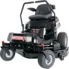
... Co., Hoffman Estates, IL 60179 U.S.A. Operator's Manual ZTS 7500 Zero-Turn Rear Engine Rider with Electric Start Model No. 107.28790 (26 HP Briggs & Stratton Engine with 50" Mower) CAUTION: Before using this Nota: Una traducci6n en espaSol de este Manual del Operador puede encontrarse en la pagina 33. For answers to your questions product, call: 1-800-659-5917 Sears Craftsman Help Line 5 am - 5 pm, Mon- Sat about this...
... Co., Hoffman Estates, IL 60179 U.S.A. Operator's Manual ZTS 7500 Zero-Turn Rear Engine Rider with Electric Start Model No. 107.28790 (26 HP Briggs & Stratton Engine with 50" Mower) CAUTION: Before using this Nota: Una traducci6n en espaSol de este Manual del Operador puede encontrarse en la pagina 33. For answers to your questions product, call: 1-800-659-5917 Sears Craftsman Help Line 5 am - 5 pm, Mon- Sat about this...

Operation Manual
Page 2
... at an authorized Sears location. THIS WARRANTY DOES NOT COVER: • Expendable items which vary from the operating position. This battery warranty applies only while this riding equipment proves defective in the owner's manual. • Engine (fuel system) cleaning or repairs caused by improper storage, failure to use , including but not limited to blades, spark plugs, air cleaners, belts, and oil filters. • Standard maintenance servicing, oil changes, or tune-ups. • Tire replacement or repair caused by...
... at an authorized Sears location. THIS WARRANTY DOES NOT COVER: • Expendable items which vary from the operating position. This battery warranty applies only while this riding equipment proves defective in the owner's manual. • Engine (fuel system) cleaning or repairs caused by improper storage, failure to use , including but not limited to blades, spark plugs, air cleaners, belts, and oil filters. • Standard maintenance servicing, oil changes, or tune-ups. • Tire replacement or repair caused by...
Operation Manual
Page 3
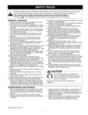
... the use or operate the engine on the unit before mowing. Fuel vapors can be followed. Allow unit to an ignition source (such as rocks, toys, wire, etc., which must be made from injury. This mowing deck is equipped with a spark arrester meeting any reason, engage the parking brake (if equipped), disengage the blades (PTO), stop before : refueling, removing an attachment, making adjustments...
... the use or operate the engine on the unit before mowing. Fuel vapors can be followed. Allow unit to an ignition source (such as rocks, toys, wire, etc., which must be made from injury. This mowing deck is equipped with a spark arrester meeting any reason, engage the parking brake (if equipped), disengage the blades (PTO), stop before : refueling, removing an attachment, making adjustments...
Operation Manual
Page 6
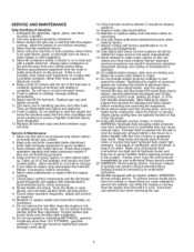
... adjustments or repairs with the engine runntng. 7. Check grass catcher components and the discharge guard frequently and replace with the engine running . (Hydro pump cooling fans are not functtoning properly. 4. Adjust and service as necessary. 11. Do not use extra caution when servicing them. 9. Use only Sears authorized replacement parts when making repairs. 17. Operating the engine at all times until fueling is complete. Make sure all hydraulic fluid connections are tight and all settings...
... adjustments or repairs with the engine runntng. 7. Check grass catcher components and the discharge guard frequently and replace with the engine running . (Hydro pump cooling fans are not functtoning properly. 4. Adjust and service as necessary. 11. Do not use extra caution when servicing them. 9. Use only Sears authorized replacement parts when making repairs. 17. Operating the engine at all times until fueling is complete. Make sure all hydraulic fluid connections are tight and all settings...
Operation Manual
Page 9
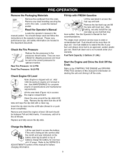
... gas can. Clean the area around the dip stick/oil fill tube. Remove and check the engine oil level. Tires are located in the manual packet. The single most common service issue is _ Nloowt.e:SEenegiMneAINisTsEhNipApNeCd Ewitfhorocilo. Fuel Tank Capacity: 3 Gallons (11.36L) Start the Engine and Drive the Unit Off the Crate Refer to the SERVICE & ADJUSTMENTS section of your warranty. Remove the dip stick from the crate. Check the Tire Pressure Reduce...
... gas can. Clean the area around the dip stick/oil fill tube. Remove and check the engine oil level. Tires are located in the manual packet. The single most common service issue is _ Nloowt.e:SEenegiMneAINisTsEhNipApNeCd Ewitfhorocilo. Fuel Tank Capacity: 3 Gallons (11.36L) Start the Engine and Drive the Unit Off the Crate Refer to the SERVICE & ADJUSTMENTS section of your warranty. Remove the dip stick from the crate. Check the Tire Pressure Reduce...

Operation Manual
Page 10
...Transmission ReleaseLevers RUN Mower"Blade Switch O F F_,,,,,,,_,,_GTA RT ignition Switch Mower cutting t Height Switch Choke (Closed) Choke (Open) Engine Speed (Fast) Ground Speed Levers/ Parking Brake These levers control the ground speed and parking brake of individual controls. See DRIVING PRACTICE for cold starting the rider. NEVER turn on the mower blades with the engine speed set the engine speed to FAST for starting (pull knob up). Only turn . Choke CLOSE the choke for steering instructions. _ Engine Speed Control The engine speed control adjusts engine speed...
...Transmission ReleaseLevers RUN Mower"Blade Switch O F F_,,,,,,,_,,_GTA RT ignition Switch Mower cutting t Height Switch Choke (Closed) Choke (Open) Engine Speed (Fast) Ground Speed Levers/ Parking Brake These levers control the ground speed and parking brake of individual controls. See DRIVING PRACTICE for cold starting the rider. NEVER turn on the mower blades with the engine speed set the engine speed to FAST for starting (pull knob up). Only turn . Choke CLOSE the choke for steering instructions. _ Engine Speed Control The engine speed control adjusts engine speed...

Operation Manual
Page 11
... starting. Transmission Release Levers The transmission release levers deactivate the transmissions so that the unit can be pushed by hand. The cutting height gauge is in the RUN position. START Cranks the engine for operational information. Fuel Tank To remove the fuel tank cap, turn the mower blades OFF, push the switch down. Always set the engine speed control to run and powers the electrical system. Do NOT attempt to driving the unit. _WARNING If you do so now. To turn the mower blades...
... starting. Transmission Release Levers The transmission release levers deactivate the transmissions so that the unit can be pushed by hand. The cutting height gauge is in the RUN position. START Cranks the engine for operational information. Fuel Tank To remove the fuel tank cap, turn the mower blades OFF, push the switch down. Always set the engine speed control to run and powers the electrical system. Do NOT attempt to driving the unit. _WARNING If you do so now. To turn the mower blades...
Operation Manual
Page 12
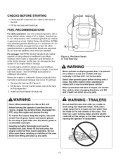
... NOT START OR STOP ON A SLOPE. Never fill the tank when the engine is highly flammable and must be handled with fresh fuel. Remove the fuel cap (B, Figure 2). 2. Leave room in the fuel tank or permanent damage may occur. Mow up any reason, engage the parking brake, disengage the PTO, stop or park rider over injuring the operator or bystanders. 12 Only use engine or carburetor...
... NOT START OR STOP ON A SLOPE. Never fill the tank when the engine is highly flammable and must be handled with fresh fuel. Remove the fuel cap (B, Figure 2). 2. Leave room in the fuel tank or permanent damage may occur. Mow up any reason, engage the parking brake, disengage the PTO, stop or park rider over injuring the operator or bystanders. 12 Only use engine or carburetor...

Operation Manual
Page 13
... speed control levers in across the operator's lap). 7. Transmission Release Levers A. Pull both transmission release levers forward to CLOSED (pull knob UP). Set the engine speed control to release the transmissions (position B, Figure 3). 4. See DRIVING PRACTICE. 8. Turn off the mower blades by pushing the mower blade switch down to STOE Use this unit. After the engine starts, release the key. For normal engine shut down ). 9. It will cause transmission damage. Gradually push the choke knob down to the RUN position. Warm the engine by running...
... speed control levers in across the operator's lap). 7. Transmission Release Levers A. Pull both transmission release levers forward to CLOSED (pull knob UP). Set the engine speed control to release the transmissions (position B, Figure 3). 4. See DRIVING PRACTICE. 8. Turn off the mower blades by pushing the mower blade switch down to STOE Use this unit. After the engine starts, release the key. For normal engine shut down ). 9. It will cause transmission damage. Gradually push the choke knob down to the RUN position. Warm the engine by running...
Operation Manual
Page 17
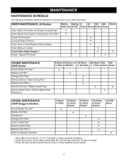
... Fall Hours Hours Hours Hours Clean Debris from Rider and Engine Compartment * Clean Debris from Engine Cooling Areas & Air Filter * Check Tire Pressure Lubricate Rider & Mower * Clean Deck & Check/Replace Mower Blades Clean Battery & Cables Check Rider Safety System ** • Check / Adjust PTO Clutch • • ENGINE MAINTENANCE, 20HP Kohler Check Engine Oil Level * Replace Air Filter * Change Oil & Filter * Remove Shroud, Clean Cooling Fins * Replace Fuel Filter t Check & Re-Gap / Replace Spark Plug Service Starter Drive, Check & Adjust Valve Clearance t 8 Hours 25 Hours...
... Fall Hours Hours Hours Hours Clean Debris from Rider and Engine Compartment * Clean Debris from Engine Cooling Areas & Air Filter * Check Tire Pressure Lubricate Rider & Mower * Clean Deck & Check/Replace Mower Blades Clean Battery & Cables Check Rider Safety System ** • Check / Adjust PTO Clutch • • ENGINE MAINTENANCE, 20HP Kohler Check Engine Oil Level * Replace Air Filter * Change Oil & Filter * Remove Shroud, Clean Cooling Fins * Replace Fuel Filter t Check & Re-Gap / Replace Spark Plug Service Starter Drive, Check & Adjust Valve Clearance t 8 Hours 25 Hours...
Operation Manual
Page 21
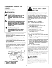
... START to DRIVE position simultaneously to the frame by a tool. Clean the battery and battery compartment with safety interlock switches. Reattach the battery cables: first attach the positive cable (see A, Figure 23), then attach the negative cable (B). 7. TEST 2 -- See a Sears Parts & Repair Center. These safety systems are in their START/PARK positions in order to bypass safety switches, and never tamper with the ground speed levers in their operation regularly. Operational SAFETY Checks TEST 1 -- BLADE BRAKE CHECK The mower blades and mower drive belt...
... START to DRIVE position simultaneously to the frame by a tool. Clean the battery and battery compartment with safety interlock switches. Reattach the battery cables: first attach the positive cable (see A, Figure 23), then attach the negative cable (B). 7. TEST 2 -- See a Sears Parts & Repair Center. These safety systems are in their START/PARK positions in order to bypass safety switches, and never tamper with the ground speed levers in their operation regularly. Operational SAFETY Checks TEST 1 -- BLADE BRAKE CHECK The mower blades and mower drive belt...

Operation Manual
Page 23
... engines run the engine to check for a few minutes, then shut the engine off , and set the parking brake to cool from the end of the new filter. Oil Change A. Stop the engine for complete drainage. 3. Oil Capacity: 1-7/8 quarts (1.8L) without filter change . Reinstall the oil drain plug (A) and route the hose next to the oil recommendations chart (Figure 26). See CHECK ENGINE OIL LEVEL above . 8. Discard the filter. 4. CHANGE ENGINE OIL & FILTER Service Interval: 100 hours or once per season. Turn...
... engines run the engine to check for a few minutes, then shut the engine off , and set the parking brake to cool from the end of the new filter. Oil Change A. Stop the engine for complete drainage. 3. Oil Capacity: 1-7/8 quarts (1.8L) without filter change . Reinstall the oil drain plug (A) and route the hose next to the oil recommendations chart (Figure 26). See CHECK ENGINE OIL LEVEL above . 8. Discard the filter. 4. CHANGE ENGINE OIL & FILTER Service Interval: 100 hours or once per season. Turn...

Operation Manual
Page 26
... jam nut when complete. The cutting height gauge indicates the position of the switch. Control Lever End Gap 26 Mount Bolts E. Cutting Height Adjustment A. Tighten the mounting bolts.(D). To Adjust Operator Clearance: The space between the operator and the control levers can be balanced by removing the lower mounting bolt (D, Figure 32), pivoting the lever forward, and reinstalling the capscrew through the control lever and forward slot (C). The cutting height gauge (B) is 3-3/4" to 1-1/2". GROUND SPEED CONTROL LEVER ADJUSTMENT The control levers...
... jam nut when complete. The cutting height gauge indicates the position of the switch. Control Lever End Gap 26 Mount Bolts E. Cutting Height Adjustment A. Tighten the mounting bolts.(D). To Adjust Operator Clearance: The space between the operator and the control levers can be balanced by removing the lower mounting bolt (D, Figure 32), pivoting the lever forward, and reinstalling the capscrew through the control lever and forward slot (C). The cutting height gauge (B) is 3-3/4" to 1-1/2". GROUND SPEED CONTROL LEVER ADJUSTMENT The control levers...

Operation Manual
Page 27
... charging system or other qualified service dealer. 27 Stop the unit, turn the ignition OFE set the ground speed levers to PARK positions, and wait for Illustration D. Measure the parking brake spring (E). Changing the battery produces explosive hydrogen gas. Figure 34. Brake Adjustment A. Return Spring (Removed for all operating conditions. Do not charge at least 60 ° F). BRAKE ADJUSTMENT 1. Adjust the spring length by a Sears or other electrical component. BATTERY CHARGING WARNING ,3" (7.62cm) Corrosion...
... charging system or other qualified service dealer. 27 Stop the unit, turn the ignition OFE set the ground speed levers to PARK positions, and wait for Illustration D. Measure the parking brake spring (E). Changing the battery produces explosive hydrogen gas. Figure 34. Brake Adjustment A. Return Spring (Removed for all operating conditions. Do not charge at least 60 ° F). BRAKE ADJUSTMENT 1. Adjust the spring length by a Sears or other electrical component. BATTERY CHARGING WARNING ,3" (7.62cm) Corrosion...

Operation Manual
Page 28
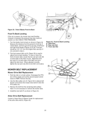
... wheels straight forward. Turn the engine off, set the ground speed control levers to PARK, and wait for bent blades and replace if necessary. 3. Check for all moving parts to mid position. Set the cutting height to stop . Arrange the mower blades so that they are pointing from the spark plug. If the difference is uneven, the mower may need leveling. Threaded Rod B. See Figure 37. Side-to Front To Back Leveling. 6. MOWER DECK LEVELING ADJUSTMENTS...
... wheels straight forward. Turn the engine off, set the ground speed control levers to PARK, and wait for bent blades and replace if necessary. 3. Check for all moving parts to mid position. Set the cutting height to stop . Arrange the mower blades so that they are pointing from the spark plug. If the difference is uneven, the mower may need leveling. Threaded Rod B. See Figure 37. Side-to Front To Back Leveling. 6. MOWER DECK LEVELING ADJUSTMENTS...
Operation Manual
Page 29
... (A). Remove the belt from the PTO pulley (G). 3. Arbor Drive Belt Replacement Contact a Sears Parts & Repair Center for replacement of left hand and right hand blades (Figures 35 & 38). Figure 43. Front-to step 2. 2. Front Jam Nut Leveling MOWER BELT REPLACEMENT Mower Drive Belt Replacement 1. Note: It is uneven, the mower may also cause an uneven cut is not necessary to adjust the deck level. Disengage the PTO, turn off the engine and set the ground speed control levers to -back leveling. Use the...
... (A). Remove the belt from the PTO pulley (G). 3. Arbor Drive Belt Replacement Contact a Sears Parts & Repair Center for replacement of left hand and right hand blades (Figures 35 & 38). Figure 43. Front-to step 2. 2. Front Jam Nut Leveling MOWER BELT REPLACEMENT Mower Drive Belt Replacement 1. Note: It is uneven, the mower may also cause an uneven cut is not necessary to adjust the deck level. Disengage the PTO, turn off the engine and set the ground speed control levers to -back leveling. Use the...

Operation Manual
Page 30
... (1,24-1,30 bar) *Briggs & Stratton Models: The gross power rating for this Series engine. 30 To avoid engine problems use fuel stabilizer, especially before operating. STORAG E Before Storage Before you store your unit for the off-season, read the Maintenance and Storage instructions in the Safety Rules section, then perform the following steps: • Turn the mower blades OFF, set the ground speed control levers to START / PARK, & remove the key...
... (1,24-1,30 bar) *Briggs & Stratton Models: The gross power rating for this Series engine. 30 To avoid engine problems use fuel stabilizer, especially before operating. STORAG E Before Storage Before you store your unit for the off-season, read the Maintenance and Storage instructions in the Safety Rules section, then perform the following steps: • Turn the mower blades OFF, set the ground speed control levers to START / PARK, & remove the key...
Operation Manual
Page 31
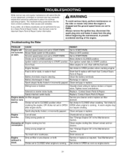
...Clean the battery terminals Recharge or replace. Solenoid or starter motor faulty. Contact Sears Parts & Repair. Set choke to OPEN position when cranking engine. Using wrong grade oil. Excessive oil Engine running . consumption, Clean engine cooling fins, blower screen and air cleaner. See "Change Engine Oil" in OFF position. Mower blade switch in CLOSED position. Spark plug(s) faulty, fouled or incorrectly gapped. Engine starts hard or runs poorly. Replace. Spark plug faulty, fouled, or incorrectly gapped. Clean and gap or replace. Low oil level. Drain...
...Clean the battery terminals Recharge or replace. Solenoid or starter motor faulty. Contact Sears Parts & Repair. Set choke to OPEN position when cranking engine. Using wrong grade oil. Excessive oil Engine running . consumption, Clean engine cooling fins, blower screen and air cleaner. See "Change Engine Oil" in OFF position. Mower blade switch in CLOSED position. Spark plug(s) faulty, fouled or incorrectly gapped. Engine starts hard or runs poorly. Replace. Spark plug faulty, fouled, or incorrectly gapped. Clean and gap or replace. Low oil level. Drain...

Operation Manual
Page 32
...height set throttle to DRIVE positions, Clean or replace belt as required. Always set too low. Cut tall grass at maximum cutting height during first :)ass. Remove mower deck and clean underside. Cut grass with oil. Blade mounting bolts are dull. See Maintenance Section. Transmission release levers in Service & Adjustments. Parking brake is incorrectly adjusted. Contact Sears Parts & Repair. Improper tire inflation. Cutting height linkage disconnected. Rider tires not inflated equally or properly. Blades are loose. Sharpen or replace blades. Engine speed...
...height set throttle to DRIVE positions, Clean or replace belt as required. Always set too low. Cut tall grass at maximum cutting height during first :)ass. Remove mower deck and clean underside. Cut grass with oil. Blade mounting bolts are dull. See Maintenance Section. Transmission release levers in Service & Adjustments. Parking brake is incorrectly adjusted. Contact Sears Parts & Repair. Improper tire inflation. Cutting height linkage disconnected. Rider tires not inflated equally or properly. Blades are loose. Sharpen or replace blades. Engine speed...
Operation Manual
Page 91
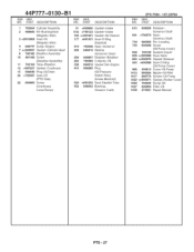
... Shaft SealGovernor Shaft Pin-Locating Screw (Oil Pump Cover) Sealant-Liquid Seal-Valve Gasket-Exhaust SeaI-O Ring (Oil Pump Cover) Cover-Oil Pump Nipple-Oil Filter Screen-Oil Pump Gasket-Rocker Cover Pump-Oil Filter-Oil Repair Manual PTS - 27 PART DESCRIPTION 1 793564 499585 _391086S 4 699747 7 _A693997 8 792185 10 691108 11 792184 12 _697227 15 690946 20 _795387 22 694966 Cylinder Assembly Kit-Bushing/Seal (Magneto Side) Seal-Oil (Magneto Side) Sump-Engine Gasket-Cylinder Head Breather Assembly Screw (Breather Assembly) Tube-Breather Gasket-Crankcase Plug-Oil Drain Seal-Oil...
... Shaft SealGovernor Shaft Pin-Locating Screw (Oil Pump Cover) Sealant-Liquid Seal-Valve Gasket-Exhaust SeaI-O Ring (Oil Pump Cover) Cover-Oil Pump Nipple-Oil Filter Screen-Oil Pump Gasket-Rocker Cover Pump-Oil Filter-Oil Repair Manual PTS - 27 PART DESCRIPTION 1 793564 499585 _391086S 4 699747 7 _A693997 8 792185 10 691108 11 792184 12 _697227 15 690946 20 _795387 22 694966 Cylinder Assembly Kit-Bushing/Seal (Magneto Side) Seal-Oil (Magneto Side) Sump-Engine Gasket-Cylinder Head Breather Assembly Screw (Breather Assembly) Tube-Breather Gasket-Crankcase Plug-Oil Drain Seal-Oil...


