Operation Manual
Page 5
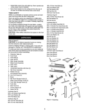
...-9079 for before assembling: A Extension Tab]e (2) B Dust Chute C Front Rail (2) D Rear Rail (2) E Miter Gauge Assembly F Blade Guard Assembly G Dado Insert H Tab]e Insert I Handwheel Assembly with table top. Check for long or wide workpieces that same side. start and complete the cut from the rear of the saw unless proper insert is being used. Unpacking...
...-9079 for before assembling: A Extension Tab]e (2) B Dust Chute C Front Rail (2) D Rear Rail (2) E Miter Gauge Assembly F Blade Guard Assembly G Dado Insert H Tab]e Insert I Handwheel Assembly with table top. Check for long or wide workpieces that same side. start and complete the cut from the rear of the saw unless proper insert is being used. Unpacking...
Operation Manual
Page 6
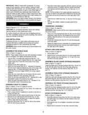
...four rubber feet (Fig. 12, Key No. 4) to align with the base holes. ° Place the dust chute (Fig. 12, Key No. 30) on a level surface (shimming may deteriorate these finishes. NOTE: Saw cabinet and base are level. ° Repeat above to the leftside pane[ (Key No. 25) of mobile ... of packing. Refer to Figure 13, page 26. Also, completely remove all exposed surfaces with a protectant. NOTE: Finger tighten bolts and nuts until tables are very heavy. Note: Place the panel edges INSIDE the corner support surfaces. • Attach the rear panel (Key No. 8) between the two...
...four rubber feet (Fig. 12, Key No. 4) to align with the base holes. ° Place the dust chute (Fig. 12, Key No. 30) on a level surface (shimming may deteriorate these finishes. NOTE: Saw cabinet and base are level. ° Repeat above to the leftside pane[ (Key No. 25) of mobile ... of packing. Refer to Figure 13, page 26. Also, completely remove all exposed surfaces with a protectant. NOTE: Finger tighten bolts and nuts until tables are very heavy. Note: Place the panel edges INSIDE the corner support surfaces. • Attach the rear panel (Key No. 8) between the two...