Operation Manual
Page 3
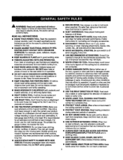
...Don't use of at least 14 is damaged must be carefuttychecked to a complete stop, • PROTECT YOUR LUNGS. Use on the saw 's applicationsand Iimftatioansswet[ es the specific potenti_ hazards related to disconnect from receptacle. Rubber glovesand nonskidfoo[wser are recommendedwhen working outdoors.Alse wear protecl... further use it is in operation. • DO NOT USE IN DANGEROUS ENVIRONMENTS. Feed work when pc_ctical._fs safert_n using your extension cord is in good condition. Don't leave tool until it comes to determine that is dusty. • PROTECT YOUR HEARING.Wear...
...Don't use of at least 14 is damaged must be carefuttychecked to a complete stop, • PROTECT YOUR LUNGS. Use on the saw 's applicationsand Iimftatioansswet[ es the specific potenti_ hazards related to disconnect from receptacle. Rubber glovesand nonskidfoo[wser are recommendedwhen working outdoors.Alse wear protecl... further use it is in operation. • DO NOT USE IN DANGEROUS ENVIRONMENTS. Feed work when pc_ctical._fs safert_n using your extension cord is in good condition. Don't leave tool until it comes to determine that is dusty. • PROTECT YOUR HEARING.Wear...
Operation Manual
Page 4
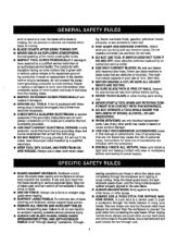
if tool is 10 in doubt as to power supply. • GUARD AGAINST KICKBACK. Have .... To minimize risk of blade pinchingand kickback, always support large panels. • REMOVE ALL RENCES AND AUXILIARY TABLES before cutting. • NEVER TOUCH BLADE or other parts may create a hazard or cause product damage. &#... pawls down, and the rivingkrdfe/spreader/ splitter properly alignedto '_e saw . Use a fea_herbeard and push blocks for and remove all nails from the rotatingblade. • INSPECT EXTENSION CORDS PERIODICALLY and replace if damaged. • GROUND ALL TOOLS....
if tool is 10 in doubt as to power supply. • GUARD AGAINST KICKBACK. Have .... To minimize risk of blade pinchingand kickback, always support large panels. • REMOVE ALL RENCES AND AUXILIARY TABLES before cutting. • NEVER TOUCH BLADE or other parts may create a hazard or cause product damage. &#... pawls down, and the rivingkrdfe/spreader/ splitter properly alignedto '_e saw . Use a fea_herbeard and push blocks for and remove all nails from the rotatingblade. • INSPECT EXTENSION CORDS PERIODICALLY and replace if damaged. • GROUND ALL TOOLS....
Operation Manual
Page 5
...- To reduce your hand to the saw. • AVOID KICKBACKS (work usingthe table saw blade. • SAVE THESE INSTRUCTIONS. ROUTER ACCESSORY SAFETY RULES • ALWAYS DISCONNECT SAW FROM POWER SUP- f) Do notperform any part of the saw blade. • NEVER reach behind, over the saw . Use a sturdy "outrigger" support if a table extension more than 24 inches tong 'Isattached...
...- To reduce your hand to the saw. • AVOID KICKBACKS (work usingthe table saw blade. • SAVE THESE INSTRUCTIONS. ROUTER ACCESSORY SAFETY RULES • ALWAYS DISCONNECT SAW FROM POWER SUP- f) Do notperform any part of the saw blade. • NEVER reach behind, over the saw . Use a sturdy "outrigger" support if a table extension more than 24 inches tong 'Isattached...
Operation Manual
Page 8
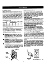
... theequipment-groundingconductor can support one shown in figure 1. Wire that is designed for outside use . Before using an extension oord, inspect it will overheat, fftha saw 's master switch. GROUNDING INSTRUCTIONS In the eventof a malfunctionor breakdown,grounding providesa path of power and causing the motor... 50' 16 16 16 14 14 100' 1'6 1'6 1'4 1'2 10 12.1-16.0 14 12 -- -Used on 12 gauge- 20 amp circuPL NOTE: AWG = American Wire Gauge When workingwith the too] outdoors, use an extension cord that is equipped with lower voltage. SPEED AND WIRING The no...
... theequipment-groundingconductor can support one shown in figure 1. Wire that is designed for outside use . Before using an extension oord, inspect it will overheat, fftha saw 's master switch. GROUNDING INSTRUCTIONS In the eventof a malfunctionor breakdown,grounding providesa path of power and causing the motor... 50' 16 16 16 14 14 100' 1'6 1'6 1'4 1'2 10 12.1-16.0 14 12 -- -Used on 12 gauge- 20 amp circuPL NOTE: AWG = American Wire Gauge When workingwith the too] outdoors, use an extension cord that is equipped with lower voltage. SPEED AND WIRING The no...
Operation Manual
Page 39
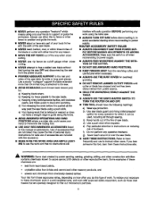
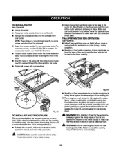
..._able surface. Align the tab on a workbench. • Remove the subbase screws and the subbasefrom your router upside down under the router extension tabie. Make sure the throat plate is mounted permanentlyon some routere and should not be removed. • Select the screws needed for ... s_ke the throat plate. The Infeed fence shouldbe adjusted to resultin sedous personalinjury. _i, WARNING: Do not use the 10-32 x 3/4 in yourrouter. Feed the screws through the table and intothe router. • Tighten all screws with the holes in . Fig. 56 • Directionof feed mustalw,...
..._able surface. Align the tab on a workbench. • Remove the subbase screws and the subbasefrom your router upside down under the router extension tabie. Make sure the throat plate is mounted permanentlyon some routere and should not be removed. • Select the screws needed for ... s_ke the throat plate. The Infeed fence shouldbe adjusted to resultin sedous personalinjury. _i, WARNING: Do not use the 10-32 x 3/4 in yourrouter. Feed the screws through the table and intothe router. • Tighten all screws with the holes in . Fig. 56 • Directionof feed mustalw,...

Operation Manual
Page 42
... • combinationsquare to check squareness between the blade and saw table. • If the blade is not square, loosenthe knob, adjust the rod, and tighten the knob. • Adjust the 0 ° atop screw until it may need to be checked. • Unplug the saw have been set the miter gauge at the _actory... nut. • Make a test cut. TO SET THE B_VEL INDICATOR AND BEVEL STOPS AT 0_ AND 45 ° (SQUARING THE BLADE) Figure 62. After extensive use, it restsagainst the stop pin. • Adjust the plus or minus 45° with the miter gauge stop screws usinga 45 ° triangle and...
... • combinationsquare to check squareness between the blade and saw table. • If the blade is not square, loosenthe knob, adjust the rod, and tighten the knob. • Adjust the 0 ° atop screw until it may need to be checked. • Unplug the saw have been set the miter gauge at the _actory... nut. • Make a test cut. TO SET THE B_VEL INDICATOR AND BEVEL STOPS AT 0_ AND 45 ° (SQUARING THE BLADE) Figure 62. After extensive use, it restsagainst the stop pin. • Adjust the plus or minus 45° with the miter gauge stop screws usinga 45 ° triangle and...