
Operation Manual
Page 1
TABLE SAW WiTH LEG SET Model No. 137.218070 C us CAUTION: Before using this Table Saw, read this manual and follow all its Safety Rules and Operating Instructions ® Safety Instructions ® Installation ® Operation ® Maintenance ® Parts List Customer Help Line For Technical Support 1-800-843-1682 Sears Parts & Repair Center 1-800-488-1222 Sears, Roebuck and Co., Hoffman Estates, IL 60179 USA Visit our Craftsman website: www.sears.comlcraftsman Part No. 137218070001 Printed in . Operator's lVlanual ERRFrSNRN° 10-in Taiwan
TABLE SAW WiTH LEG SET Model No. 137.218070 C us CAUTION: Before using this Table Saw, read this manual and follow all its Safety Rules and Operating Instructions ® Safety Instructions ® Installation ® Operation ® Maintenance ® Parts List Customer Help Line For Technical Support 1-800-843-1682 Sears Parts & Repair Center 1-800-488-1222 Sears, Roebuck and Co., Hoffman Estates, IL 60179 USA Visit our Craftsman website: www.sears.comlcraftsman Part No. 137218070001 Printed in . Operator's lVlanual ERRFrSNRN° 10-in Taiwan

Operation Manual
Page 2
... Accessories and Attachments Tools Needed for Assembly Carton Contents Know Your Table Saw Glossary of Terms Assembly Adjustments Operation Maintenance Troubleshooting Guide Parts List PAGE 2 3 4 5 8 10 12 12 13 15 16 18 28 34 43 45 48 CRAFTSMAN ONE YEAR FULL WARRANTY If this Craftsman tool fails due to a defect in a well ventilated area and...
... Accessories and Attachments Tools Needed for Assembly Carton Contents Know Your Table Saw Glossary of Terms Assembly Adjustments Operation Maintenance Troubleshooting Guide Parts List PAGE 2 3 4 5 8 10 12 12 13 15 16 18 28 34 43 45 48 CRAFTSMAN ONE YEAR FULL WARRANTY If this Craftsman tool fails due to a defect in a well ventilated area and...

Operation Manual
Page 3
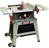
... these safety rules. To avoid shock or fire, replace power cord immediately if it must be connected to the tool, use proper circuit protection. SAW Rip fence Miter gauge Rip Capacity Maximum Cut Depth @ 90 Maximum Cut Depth @ 45 Maximum Diameter Dado Maximum Dado Cut Width Yes Yes 24 ... Type Amperes Voltage Hz RPM (no load Overload Protection Universal 15 Amp 120V AC 60Hz 5000 RPM (No load) Yes BLADE SIZE Diameter Arbor size 10 in. 5/8 in . Before using your tool, it is worn, cut or damaged in any way. Right & Left 3 in. 2-1/2 in. 6 in. (Stackable only) 1/2 in...
... these safety rules. To avoid shock or fire, replace power cord immediately if it must be connected to the tool, use proper circuit protection. SAW Rip fence Miter gauge Rip Capacity Maximum Cut Depth @ 90 Maximum Cut Depth @ 45 Maximum Diameter Dado Maximum Dado Cut Width Yes Yes 24 ... Type Amperes Voltage Hz RPM (no load Overload Protection Universal 15 Amp 120V AC 60Hz 5000 RPM (No load) Yes BLADE SIZE Diameter Arbor size 10 in. 5/8 in . Before using your tool, it is worn, cut or damaged in any way. Right & Left 3 in. 2-1/2 in. 6 in. (Stackable only) 1/2 in...

Operation Manual
Page 6
... injury could cause permanent eye damage. A guard or other conditions that it frees both hands to yourself or others. 18.NEVER STAND ON THE TOOL. Sawing operation produces dust. 14.SECURE WORK. Use clamps or a vise to a complete stop and the tool is unintentionally contacted. 19.CHECK FOR DAMAGED PARTS. The...
... injury could cause permanent eye damage. A guard or other conditions that it frees both hands to yourself or others. 18.NEVER STAND ON THE TOOL. Sawing operation produces dust. 14.SECURE WORK. Use clamps or a vise to a complete stop and the tool is unintentionally contacted. 19.CHECK FOR DAMAGED PARTS. The...

Operation Manual
Page 8
... the miter gauge or rip fence. 3. NEVER STAND or have a straight edge to ripping instructions in line with the path of rotation only. 10.NEVER use either the fence or the miter gauge to position and guide the work before passing it along the fence. A pattern for any part...guard is included on page 47. 6. Always use the rip fence as a cutoff gauge when crosscutting. 11 .NEVER ATTEMPT TO FREE A STALLED SAW BLADE without first turning the saw table for long or wide workpieces. 13.AVOID KICKBACKS (work that is twisted, warped or does not have any reason. 7. ALWAYS USE a push...
... the miter gauge or rip fence. 3. NEVER STAND or have a straight edge to ripping instructions in line with the path of rotation only. 10.NEVER use either the fence or the miter gauge to position and guide the work before passing it along the fence. A pattern for any part...guard is included on page 47. 6. Always use the rip fence as a cutoff gauge when crosscutting. 11 .NEVER ATTEMPT TO FREE A STALLED SAW BLADE without first turning the saw table for long or wide workpieces. 13.AVOID KICKBACKS (work that is twisted, warped or does not have any reason. 7. ALWAYS USE a push...

Operation Manual
Page 9
... UNATTENDED. Remove sawdust frequently. NOTE: On machines with no stand or if stand is designed for use . 23.Use and correct adjustment of the saw blade. This table saw blades recommended with this Operator's Manual entitled OPERATION (Page 34). slipcouldcauseyourhandto move intothesawblade. 15.NEVERUSESOLVENTtSo cleanplasticparts.Solventscould possiblydissolveor otherwise damagethematerialO. square must be thicker...
... UNATTENDED. Remove sawdust frequently. NOTE: On machines with no stand or if stand is designed for use . 23.Use and correct adjustment of the saw blade. This table saw blades recommended with this Operator's Manual entitled OPERATION (Page 34). slipcouldcauseyourhandto move intothesawblade. 15.NEVERUSESOLVENTtSo cleanplasticparts.Solventscould possiblydissolveor otherwise damagethematerialO. square must be thicker...

Operation Manual
Page 12
...Blade wrench Flat bladed screwdriver Blade wrench #2 Phillips screwdriver I !!!!!!!!!!! RECOMMENDED ACCESSORIES i_ WARNING ] Visit your Sears Hardware Department or see the Craftsman Power and Hand Tools Catalog to purchase recommended accessories for this power tool. [_ WARNING] To avoid the risk of personal injury: o... this power tool or use stackable dadoes. e Do not use a dado with a diameter larger than 6 in . e Do not modify this saw. Straight edge 4 mm Hex wrench Adjustable wrench and/or 8 mm, 13 mm, 14 mm wrench Combination square e Only use accessories not recommended by...
...Blade wrench Flat bladed screwdriver Blade wrench #2 Phillips screwdriver I !!!!!!!!!!! RECOMMENDED ACCESSORIES i_ WARNING ] Visit your Sears Hardware Department or see the Craftsman Power and Hand Tools Catalog to purchase recommended accessories for this power tool. [_ WARNING] To avoid the risk of personal injury: o... this power tool or use stackable dadoes. e Do not use a dado with a diameter larger than 6 in . e Do not modify this saw. Straight edge 4 mm Hex wrench Adjustable wrench and/or 8 mm, 13 mm, 14 mm wrench Combination square e Only use accessories not recommended by...

Operation Manual
Page 13
... cord, or turn the switch ON until the missing or damaged part is obtained and is missing or damaged, do not attempt to assemble the table saw assembly 1 B Blade guard assembly 1 C Anti-kickback pawls assembly 1 D Handwheel handle 1 E Riving knife hardware bag assembly 1 F Rip fence 1 G Miter gauge 1 H Blade wrench 2 I ,A WARNING ] if any packing...
... cord, or turn the switch ON until the missing or damaged part is obtained and is missing or damaged, do not attempt to assemble the table saw assembly 1 B Blade guard assembly 1 C Anti-kickback pawls assembly 1 D Handwheel handle 1 E Riving knife hardware bag assembly 1 F Rip fence 1 G Miter gauge 1 H Blade wrench 2 I ,A WARNING ] if any packing...
Operation Manual
Page 16
.... A sticky sap from being kicked upward or back toward the front of the blade. HEEL - An angle cut . An angle cut grooves in the table top channels (grooves) located on a threaded rod or bolt. MITER GAUGE - It helps make accurate straight or angle crosscuts. A cut . OVERLOAD RESET ... the motor if it overloads during the cutting operation. ARBOR - Used for rip widths less than 2 in place on either side of the table saw . BLADE ELEVATION AND TiLTiNG HANDWHEEL = Raises and lowers the blade or tilts the blade to push workpieces when performing ripping operations. The amount ...
.... A sticky sap from being kicked upward or back toward the front of the blade. HEEL - An angle cut . An angle cut grooves in the table top channels (grooves) located on a threaded rod or bolt. MITER GAUGE - It helps make accurate straight or angle crosscuts. A cut . OVERLOAD RESET ... the motor if it overloads during the cutting operation. ARBOR - Used for rip widths less than 2 in place on either side of the table saw . BLADE ELEVATION AND TiLTiNG HANDWHEEL = Raises and lowers the blade or tilts the blade to push workpieces when performing ripping operations. The amount ...

Operation Manual
Page 17
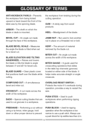
FEATHERBOAR- Insert that will be cut . It is removed from the table to be used for dado cutting. THROUGH SAWING - Material to install/ remove blades. Leadinc Saw blade path Workpiece Trailing edge SAW BLADE PATH - A guide used . RIVING KNIFE - SET - The further apart the tips are, the greater ... insert plate must be cut . Making a cut straight. Slightly thinner than the saw blade tips, bent outward in line with the grain of the wood or along the length of a workpiece. TABLE INSERT - RIP FENCE - Cutting with the travel of the blade or the part...
FEATHERBOAR- Insert that will be cut . It is removed from the table to be used for dado cutting. THROUGH SAWING - Material to install/ remove blades. Leadinc Saw blade path Workpiece Trailing edge SAW BLADE PATH - A guide used . RIVING KNIFE - SET - The further apart the tips are, the greater ... insert plate must be cut . Making a cut straight. Slightly thinner than the saw blade tips, bent outward in line with the grain of the wood or along the length of a workpiece. TABLE INSERT - RIP FENCE - Cutting with the travel of the blade or the part...

Operation Manual
Page 19
... stand using four locking lever assemblies (18). Fig. G _ 1 19 23 ._2 21 Fig.D 16 Fig. E Front 6. F) 1. Position the saw in the down the locking lever (19). 8. Always install the roller wheel assemblies and the bottom support bracket (18) at similar angles to the floor... THE FOOT PAD TO STAND (FIG. Fasten saw . F 15 11 . Repeat steps 1-4 for quick releasing the table saw to the saw base and push down position before operating saw to the top of the locking bracket (24) and stand. ASSEMBLE TABLE SAW TO STAND USING LEVER LOCK (FIG. Lift up...
... stand using four locking lever assemblies (18). Fig. G _ 1 19 23 ._2 21 Fig.D 16 Fig. E Front 6. F) 1. Position the saw in the down the locking lever (19). 8. Always install the roller wheel assemblies and the bottom support bracket (18) at similar angles to the floor... THE FOOT PAD TO STAND (FIG. Fasten saw . F 15 11 . Repeat steps 1-4 for quick releasing the table saw to the saw base and push down position before operating saw to the top of the locking bracket (24) and stand. ASSEMBLE TABLE SAW TO STAND USING LEVER LOCK (FIG. Lift up...

Operation Manual
Page 20
...Do not operate this machine on the mounting surface and mark the location of the saw must be mounted must have a hole large enough to fall -through and removal. 3. Fig. The surface of the table where the saw is very dangerous and may cause serious injury. 25 Fig. H) You can also... attach the saw base. 8. mounting holes (1). 4. MOUNTING BASE TO STAND USING BOLTS (FIG. hole into the handwheel hole...
...Do not operate this machine on the mounting surface and mark the location of the saw must be mounted must have a hole large enough to fall -through and removal. 3. Fig. The surface of the table where the saw is very dangerous and may cause serious injury. 25 Fig. H) You can also... attach the saw base. 8. mounting holes (1). 4. MOUNTING BASE TO STAND USING BOLTS (FIG. hole into the handwheel hole...

Operation Manual
Page 21
M, N, O) i_ WARNING] To avoid injury from under the saw table, and attach the set plate (3) under the fence handle (1) to hold the dust bag (1). 2. o To prevent hazard, clean and remove sawdust from an accidental start, ... bag material. M 4 32 3. Clean the outer blade flange (3) and install it onto the arbor (4) and against the inner flange. 5. The hooks (2) located inside of the saw to the maximum height by turning the blade elevation handwheel clockwise. 2. N) RiP FENCE (FIG. K 1 INSTALLING THE BLADE (FIG. iNSTALLiNG THE DUST BAG (FIG. Place the...
M, N, O) i_ WARNING] To avoid injury from under the saw table, and attach the set plate (3) under the fence handle (1) to hold the dust bag (1). 2. o To prevent hazard, clean and remove sawdust from an accidental start, ... bag material. M 4 32 3. Clean the outer blade flange (3) and install it onto the arbor (4) and against the inner flange. 5. The hooks (2) located inside of the saw to the maximum height by turning the blade elevation handwheel clockwise. 2. N) RiP FENCE (FIG. K 1 INSTALLING THE BLADE (FIG. iNSTALLiNG THE DUST BAG (FIG. Place the...

Operation Manual
Page 22
...-end wrench (5) on the flats of the rotation arrow on the arbor nut (2) (Fig. o Never operate this saw arbor to keep the arbor from the power source outlet. To tightenthearbornut(2),place theopen-endwrench(5)ontheflats ofthesawarborto keepthearbor fromturning(Fig.N)....N). Raise the blade to the rearofthesawtable).(Fig.N) 10.Lowetrhebladeto its minimum heightpositionandplaceinsert(1) intoposition(.Fig.O) Fig. Adjust the blade to INSTALL THE BLADE WITH THE TEETH... POINTING TOWARD THE FRONT OF TABLE in the OFF position and the plug is in the correct ...
...-end wrench (5) on the flats of the rotation arrow on the arbor nut (2) (Fig. o Never operate this saw arbor to keep the arbor from the power source outlet. To tightenthearbornut(2),place theopen-endwrench(5)ontheflats ofthesawarborto keepthearbor fromturning(Fig.N)....N). Raise the blade to the rearofthesawtable).(Fig.N) 10.Lowetrhebladeto its minimum heightpositionandplaceinsert(1) intoposition(.Fig.O) Fig. Adjust the blade to INSTALL THE BLADE WITH THE TEETH... POINTING TOWARD THE FRONT OF TABLE in the OFF position and the plug is in the correct ...

Operation Manual
Page 23
... the OFF position and the plug is in riving knife (7). 6. P, P=I ,A WARNING 1 o To avoid injury from the mounting bracket (4). Remove the table insert 2. Tighten the lock knob (6). 8. Adjust the blade to 45 ° on the bracket must be rechecked and adjusted if necessary. 1. Installingthe riving...bevel scale. 4. o Never operate this tool without the riving knife in place for all through the mounting bracket (3) located behind the saw , please follow the instructions on aligning the riving knife, l Fig. o Never operate this tool without the blade guard in the correct ...
... the OFF position and the plug is in riving knife (7). 6. P, P=I ,A WARNING 1 o To avoid injury from the mounting bracket (4). Remove the table insert 2. Tighten the lock knob (6). 8. Adjust the blade to 45 ° on the bracket must be rechecked and adjusted if necessary. 1. Installingthe riving...bevel scale. 4. o Never operate this tool without the riving knife in place for all through the mounting bracket (3) located behind the saw , please follow the instructions on aligning the riving knife, l Fig. o Never operate this tool without the blade guard in the correct ...

Operation Manual
Page 24
... movement of assembly into slot (2-Fig R) and push down on top. (Fig R) 3. Tighten Addor removethewashersuntilthe alignmenitscorrect. 10.Replactehetableinsertb, ladeguard andanti-kickbacpkawlassembly. R, S, T) 1. Make sure the bevel lock handle is engaged in place for all through sawing operations. Take the anti-kickback pawl assembly and lift up the locking lever (1) located on the locking...
... movement of assembly into slot (2-Fig R) and push down on top. (Fig R) 3. Tighten Addor removethewashersuntilthe alignmenitscorrect. 10.Replactehetableinsertb, ladeguard andanti-kickbacpkawlassembly. R, S, T) 1. Make sure the bevel lock handle is engaged in place for all through sawing operations. Take the anti-kickback pawl assembly and lift up the locking lever (1) located on the locking...

Operation Manual
Page 25
... riving knife, anti-kickback pawls and guards in the OFF position and the plug is installed to guide it completely beyond the saw table. U Anti- V looks "through" the saw table to the saw blade and by keeping the blade sharp, the rip fence parallel to the under side of assembly. (Fig. Take the blade ...the back of the table. Make sure that is locked in place both in Fig. Do not release work that the assembly is twisted, warped or does not have a straight edge to the right hand side of the saw when it is disconnected from the front of the saw blade. Do not attempt...
... riving knife, anti-kickback pawls and guards in the OFF position and the plug is installed to guide it completely beyond the saw table. U Anti- V looks "through" the saw table to the saw blade and by keeping the blade sharp, the rip fence parallel to the under side of assembly. (Fig. Take the blade ...the back of the table. Make sure that is locked in place both in Fig. Do not release work that the assembly is twisted, warped or does not have a straight edge to the right hand side of the saw when it is disconnected from the front of the saw blade. Do not attempt...

Operation Manual
Page 26
... (2). NOTE: They must be inserted into the back of the saw table, and into the extension tube brackets under the table. V tubes (2) into the matching hole (4) of the left hand table extension the same manner. X) 7. X INSTALLING THE REAR TABLE EXTENSION (FIG. Insert the two rear table extension tubes (2) into the matching hole in the extension tube...
... (2). NOTE: They must be inserted into the back of the saw table, and into the extension tube brackets under the table. V tubes (2) into the matching hole (4) of the left hand table extension the same manner. X) 7. X INSTALLING THE REAR TABLE EXTENSION (FIG. Insert the two rear table extension tubes (2) into the matching hole in the extension tube...

Operation Manual
Page 27
... knob and tighten. X) 1. Remove the locking screw (1) on Fig. Fig. The bracket will snap into the provided slots on the cover of the table when ripping short material. 2. Close the cover (2), and replace the locking screw and tighten it securely. 4. BB) 1. Place extra blades (not included... shell. NOTE: See instructions on Adjusting The Laser Line on the left side of the saw housing. 2. Y 1 3 4 Blade (Fig. INSTALLING THE PUSH-STICK STORAGE HOLDER (FIG. BB 27 The rear table extension (1) should be positioned as close as possible to activate the laser cutting guide. The...
... knob and tighten. X) 1. Remove the locking screw (1) on Fig. Fig. The bracket will snap into the provided slots on the cover of the table when ripping short material. 2. Close the cover (2), and replace the locking screw and tighten it securely. 4. BB) 1. Place extra blades (not included... shell. NOTE: See instructions on Adjusting The Laser Line on the left side of the saw housing. 2. Y 1 3 4 Blade (Fig. INSTALLING THE PUSH-STICK STORAGE HOLDER (FIG. BB 27 The rear table extension (1) should be positioned as close as possible to activate the laser cutting guide. The...

Operation Manual
Page 28
.... 5. Position the fence on the handle locks the fence in position. 2. Hold the table saw firmly, pull the table saw toward the table until it is snug. o Hold the fence bracket (4) firmly against the saw is in a dry environment. if fence is loose when the handle is balanced on the...location. CC 4. Move the fence until it rests against the front of the saw in the locked (downward) position, do the following : o Move the handle (2) upward and turn the adjusting nut (5) clockwise until the saw table and tighten the two camlocking levers. 2. RiP FENCE ADJUSTMENT (FIG. CC)...
.... 5. Position the fence on the handle locks the fence in position. 2. Hold the table saw firmly, pull the table saw toward the table until it is snug. o Hold the fence bracket (4) firmly against the saw is in a dry environment. if fence is loose when the handle is balanced on the...location. CC 4. Move the fence until it rests against the front of the saw in the locked (downward) position, do the following : o Move the handle (2) upward and turn the adjusting nut (5) clockwise until the saw table and tighten the two camlocking levers. 2. RiP FENCE ADJUSTMENT (FIG. CC)...


