
Operation Manual
Page 1
Operator's lVlanual ERRFrSNRN° 10-in Taiwan TABLE SAW WiTH LEG SET Model No. 137.218070 C us CAUTION: Before using this Table Saw, read this manual and follow all its Safety Rules and Operating Instructions ® Safety Instructions ® Installation ® Operation ® Maintenance ® Parts List Customer Help Line For Technical Support 1-800-843-1682 Sears Parts & Repair Center 1-800-488-1222 Sears, Roebuck and Co., Hoffman Estates, IL 60179 USA Visit our Craftsman website: www.sears.comlcraftsman Part No. 137218070001 Printed in .
Operator's lVlanual ERRFrSNRN° 10-in Taiwan TABLE SAW WiTH LEG SET Model No. 137.218070 C us CAUTION: Before using this Table Saw, read this manual and follow all its Safety Rules and Operating Instructions ® Safety Instructions ® Installation ® Operation ® Maintenance ® Parts List Customer Help Line For Technical Support 1-800-843-1682 Sears Parts & Repair Center 1-800-488-1222 Sears, Roebuck and Co., Hoffman Estates, IL 60179 USA Visit our Craftsman website: www.sears.comlcraftsman Part No. 137218070001 Printed in .

Operation Manual
Page 2
... Accessories and Attachments Tools Needed for Assembly Carton Contents Know Your Table Saw Glossary of Terms Assembly Adjustments Operation Maintenance Troubleshooting Guide Parts List PAGE 2 3 4 5 8 10 12 12 13 15 16 18 28 34 43 45 48 CRAFTSMAN ONE YEAR FULL WARRANTY If this Craftsman tool fails due to a defect in a well ventilated area and...
... Accessories and Attachments Tools Needed for Assembly Carton Contents Know Your Table Saw Glossary of Terms Assembly Adjustments Operation Maintenance Troubleshooting Guide Parts List PAGE 2 3 4 5 8 10 12 12 13 15 16 18 28 34 43 45 48 CRAFTSMAN ONE YEAR FULL WARRANTY If this Craftsman tool fails due to a defect in a well ventilated area and...

Operation Manual
Page 8
... use the rip fence as a cutoff gauge when crosscutting. 11 .NEVER ATTEMPT TO FREE A STALLED SAW BLADE without first turning the saw blade. NEVER STAND or have a straight edge to guide it completely beyond the saw table for long or wide workpieces. 13.AVOID KICKBACKS (work . ,A DANGER[ FREEHAND CUTTING IS THE MAJOR...AMPUTATIONS. Do not attempt to reverse out of the saw blade. A pattern for any part of your own push stick is twisted, warped or does not have any reason. 7. DO NOT USE a molding head with the path of rotation only. 10.NEVER use either the fence or the miter gauge...
... use the rip fence as a cutoff gauge when crosscutting. 11 .NEVER ATTEMPT TO FREE A STALLED SAW BLADE without first turning the saw blade. NEVER STAND or have a straight edge to guide it completely beyond the saw table for long or wide workpieces. 13.AVOID KICKBACKS (work . ,A DANGER[ FREEHAND CUTTING IS THE MAJOR...AMPUTATIONS. Do not attempt to reverse out of the saw blade. A pattern for any part of your own push stick is twisted, warped or does not have any reason. 7. DO NOT USE a molding head with the path of rotation only. 10.NEVER use either the fence or the miter gauge...

Operation Manual
Page 9
...soft dampclothshouldbe usedto clean plasticparts. 16.MOUNyTourtablesawona benchor standbeforeperforming anycuttingoperationsR. eferto ASSEMBLYonpage20. 17"1,_WARNING ] Never cut by the saw blade and not thinner than the width of the groove cut metals or masonry products with no stand or if... IN A WELL= VENTILATED AREA. slipcouldcauseyourhandto move intothesawblade. 15.NEVERUSESOLVENTtSo cleanplasticparts.Solventscould possiblydissolveor otherwise damagethematerialO. This table saw to allow sawdust to build up in the motor area, resulting in this hole will allow sawdust to feed the...
...soft dampclothshouldbe usedto clean plasticparts. 16.MOUNyTourtablesawona benchor standbeforeperforming anycuttingoperationsR. eferto ASSEMBLYonpage20. 17"1,_WARNING ] Never cut by the saw blade and not thinner than the width of the groove cut metals or masonry products with no stand or if... IN A WELL= VENTILATED AREA. slipcouldcauseyourhandto move intothesawblade. 15.NEVERUSESOLVENTtSo cleanplasticparts.Solventscould possiblydissolveor otherwise damagethematerialO. This table saw to allow sawdust to build up in the motor area, resulting in this hole will allow sawdust to feed the...

Operation Manual
Page 13
...clean dry cloth. Apply a coat of automobile wax to make assembly easier, keep contents of Loose Parts" to the table. TABLE OF LOOSE PARTS ITEM DESCRIPTION QUANTITY A Table saw , plug in the power NOTE: To make certain all items are accounted for, before cord, or turn the ...switch ON until the missing or damaged part is obtained and is missing or damaged, do not attempt to assemble the table saw assembly 1 B Blade guard assembly 1 C Anti-kickback pawls assembly 1 D Handwheel handle 1 E Riving knife hardware bag assembly 1 F Rip fence 1 G Miter gauge...
...clean dry cloth. Apply a coat of automobile wax to make assembly easier, keep contents of Loose Parts" to the table. TABLE OF LOOSE PARTS ITEM DESCRIPTION QUANTITY A Table saw , plug in the power NOTE: To make certain all items are accounted for, before cord, or turn the ...switch ON until the missing or damaged part is obtained and is missing or damaged, do not attempt to assemble the table saw assembly 1 B Blade guard assembly 1 C Anti-kickback pawls assembly 1 D Handwheel handle 1 E Riving knife hardware bag assembly 1 F Rip fence 1 G Miter gauge...
Operation Manual
Page 16
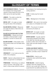
...Used to angle between 0° and 45 ° for ripping operation when the workpiece is too narrow to cut made through the face of the table saw . Prevents the workpiece from wood products. ARBOR - A simultaneous bevel and miter cut without using a rip fence, miter gauge, hold down or ... that are used for crosscutting operations that positions itself over the blade while cutting. A cut grooves in . Clear plastic cover that slides in the table top channels (grooves) located on which the blade or dado is tilted when set for rip widths less than 2 in a workpiece. COMPOUND CUT...
...Used to angle between 0° and 45 ° for ripping operation when the workpiece is too narrow to cut made through the face of the table saw . Prevents the workpiece from wood products. ARBOR - A simultaneous bevel and miter cut without using a rip fence, miter gauge, hold down or ... that are used for crosscutting operations that positions itself over the blade while cutting. A cut grooves in . Clear plastic cover that slides in the table top channels (grooves) located on which the blade or dado is tilted when set for rip widths less than 2 in a workpiece. COMPOUND CUT...

Operation Manual
Page 17
... (RPM) - The number of the workpiece. Cutting with the blade. The distance between two saw blade, it helps keep the kerf open and prevents kickback. TABLE INSERT - A metal piece of the guard assembly located behind and moves with the grain of the.... RIP FENCE - It is removed from the table to each other. THROUGH SAWING - RIVING KNIFE - Making a cut . RIPPING - Leadinc Saw blade path Workpiece Trailing edge SAW BLADE PATH - FEATHERBOAR- Material to cut . Slightly thinner than the saw blade tips, bent outward in one minute. DWhenripping...
... (RPM) - The number of the workpiece. Cutting with the blade. The distance between two saw blade, it helps keep the kerf open and prevents kickback. TABLE INSERT - A metal piece of the guard assembly located behind and moves with the grain of the.... RIP FENCE - It is removed from the table to each other. THROUGH SAWING - RIVING KNIFE - Making a cut . RIPPING - Leadinc Saw blade path Workpiece Trailing edge SAW BLADE PATH - FEATHERBOAR- Material to cut . Slightly thinner than the saw blade tips, bent outward in one minute. DWhenripping...

Operation Manual
Page 19
... the stand. Line up the lever lock cover (23) to the saw base and push down position before operating saw to the top of the locking bracket (24) and stand. Repeat steps 1-4 for quick releasing the table saw . Always install the roller wheel assemblies and the bottom support bracket (18...) at similar angles to stand using four locking lever assemblies (18). Place all bolts are provided for left -hand side. ASSEMBLE TABLE SAW TO STAND USING LEVER LOCK (FIG. Fig.D 16 Fig. Retighten these bolts once you have added the lever locks. 4. Attach the lock nuts...
... the stand. Line up the lever lock cover (23) to the saw base and push down position before operating saw to the top of the locking bracket (24) and stand. Repeat steps 1-4 for quick releasing the table saw . Always install the roller wheel assemblies and the bottom support bracket (18...) at similar angles to stand using four locking lever assemblies (18). Place all bolts are provided for left -hand side. ASSEMBLE TABLE SAW TO STAND USING LEVER LOCK (FIG. Fig.D 16 Fig. Retighten these bolts once you have added the lever locks. 4. Attach the lock nuts...

Operation Manual
Page 20
... to fall -through and removal. 3. l_k WARNING 1 Do not operate this machine on the mounting surface and mark the location of the table where the saw on the floor. Square the saw is very dangerous and may cause serious injury. 25 Fig. Mark an 11 in . Place the... handle (1) into the mounting surface. Fig. Fig. H 5. hole into the handwheel hole, and then tighten the nut against the handwheel with those drilled through the saw base to the stand using a 13 mm wrench. J The surface of the four 3/8 in stand. I ) 1. Drill 3/8 in . MOUNTING BASE TO STAND ...
... to fall -through and removal. 3. l_k WARNING 1 Do not operate this machine on the mounting surface and mark the location of the table where the saw on the floor. Square the saw is very dangerous and may cause serious injury. 25 Fig. Mark an 11 in . Place the... handle (1) into the mounting surface. Fig. Fig. H 5. hole into the handwheel hole, and then tighten the nut against the handwheel with those drilled through the saw base to the stand using a 13 mm wrench. J The surface of the four 3/8 in stand. I ) 1. Drill 3/8 in . MOUNTING BASE TO STAND ...

Operation Manual
Page 21
... flange (3). (Fig. M) Fig. Make sure the blade fits flush against the blade. (Fig. L) [_ WARNING] o Do not use this saw table, and attach the set plate (3) under the saw . (Fig. The hot chips or sparks may ignite sawdust or the bag material. The hooks (2) located inside of four legs. 1. N) 4.... (FIG. K) 1. Push down on the rip fence handle (1) so the rear holding clamp (2) is not connected to the four hooks located inside of the saw frequently. 1. L Fig. M, N, O) i_ WARNING] To avoid injury from under the fence handle (1) to cut and/or sand metals. iNSTALLiNG THE DUST...
... flange (3). (Fig. M) Fig. Make sure the blade fits flush against the blade. (Fig. L) [_ WARNING] o Do not use this saw table, and attach the set plate (3) under the saw . (Fig. The hot chips or sparks may ignite sawdust or the bag material. The hooks (2) located inside of four legs. 1. N) 4.... (FIG. K) 1. Push down on the rip fence handle (1) so the rear holding clamp (2) is not connected to the four hooks located inside of the saw frequently. 1. L Fig. M, N, O) i_ WARNING] To avoid injury from under the fence handle (1) to cut and/or sand metals. iNSTALLiNG THE DUST...

Operation Manual
Page 28
... Failure to the groove, do the following : o Loosen the two bolts (3) and lift up on the handle (2). Hold the table saw firmly, pull the table saw toward the table until the rear clamp is in a dry environment. if adjustment is moved by lifting up on the handle (2) and sliding the fence.... Fig. RiP FENCE ADJUSTMENT (FIG. DD) 1. The fence should be parallel with the miter gauge groove. MOVE THE TABLE SAW (FIG. Slide the table extension toward you until it rests against the front of the saw table and tighten the two camlocking levers. 2. Move the fence until the...
... Failure to the groove, do the following : o Loosen the two bolts (3) and lift up on the handle (2). Hold the table saw firmly, pull the table saw toward the table until the rear clamp is in a dry environment. if adjustment is moved by lifting up on the handle (2) and sliding the fence.... Fig. RiP FENCE ADJUSTMENT (FIG. DD) 1. The fence should be parallel with the miter gauge groove. MOVE THE TABLE SAW (FIG. Slide the table extension toward you until it rests against the front of the saw table and tighten the two camlocking levers. 2. Move the fence until the...

Operation Manual
Page 35
...user sights the scale off the edge of the workpiece. (It is in the front of this manual, can greatly increase the likelihood of your table saw each time, check the following: 1. NEVER USE THE TWO AT THE SAME TIME. The bevel angle lock knob is cutting either across the width ... cam locking levers. Ripping requires the use more than one rip fence during a single cut. The blade is parallel with the table, then tighten the bolts. NOTE: See page 14 for table of loose parts ITEM: S Fig. I_ WARNING] Before using the saw to rip or crosscut by freehand). QQ, RR) Fig.
...user sights the scale off the edge of the workpiece. (It is in the front of this manual, can greatly increase the likelihood of your table saw each time, check the following: 1. NEVER USE THE TWO AT THE SAME TIME. The bevel angle lock knob is cutting either across the width ... cam locking levers. Ripping requires the use more than one rip fence during a single cut. The blade is parallel with the table, then tighten the bolts. NOTE: See page 14 for table of loose parts ITEM: S Fig. I_ WARNING] Before using the saw to rip or crosscut by freehand). QQ, RR) Fig.

Operation Manual
Page 39
... operation. I WARNINi G Always position the larger surface of the miter gauge (3) and flat against the miter gauge with the blade path in line of your table saw and wait for attaching an auxiliary facing (1) to make a simple outfeed support by clamping a piece of the blade. WW 3 2 \ _/1 USING THE... {_ WARNING] To prevent serious injury: o Do not allow familiarity or frequent use of the saw blade guard. higher than the top of the blade that you can occur. 1. Hold the workpiece firmly against the table. Do not try to pull the workpiece back with the proper operation of the...
... operation. I WARNINi G Always position the larger surface of the miter gauge (3) and flat against the miter gauge with the blade path in line of your table saw and wait for attaching an auxiliary facing (1) to make a simple outfeed support by clamping a piece of the blade. WW 3 2 \ _/1 USING THE... {_ WARNING] To prevent serious injury: o Do not allow familiarity or frequent use of the saw blade guard. higher than the top of the blade that you can occur. 1. Hold the workpiece firmly against the table. Do not try to pull the workpiece back with the proper operation of the...

Operation Manual
Page 41
... and rabbets in . bb 3 To avoid the risk of the rip fence (2). 1. Before starting the table saw, lower the blade and riving knife assembly to table as shown, so the leading edges of the fence and the table. cc \ Non-through the holes in the OFF position and the plug is used when ripping...
... and rabbets in . bb 3 To avoid the risk of the rip fence (2). 1. Before starting the table saw, lower the blade and riving knife assembly to table as shown, so the leading edges of the fence and the table. cc \ Non-through the holes in the OFF position and the plug is used when ripping...

Operation Manual
Page 43
... smooth operation. Only 1/8 turn as this may create a hazard. 5. gg Use only identical replacement parts. With the saw disconnected from the power source outlet before maintaining or lubricating your own safety, turn the saw table with pitch and gum remover. 4. Fig. Use liquid dishwashing detergent and water to slide the workpiece. 3. Fig. BLADE...
... smooth operation. Only 1/8 turn as this may create a hazard. 5. gg Use only identical replacement parts. With the saw disconnected from the power source outlet before maintaining or lubricating your own safety, turn the saw table with pitch and gum remover. 4. Fig. Use liquid dishwashing detergent and water to slide the workpiece. 3. Fig. BLADE...
Operation Manual
Page 44
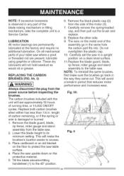
LUBRICATION 8. nallmechanical overtighten the plastic cap. usinggraphiteorsiliconeT. Always disconnect the plug from the table saw. 2. Replace both carbon brushes when either has less than 1/4 in period that reduces motor ... bricationO. partsofyourtablesawwherea pivot 10. hesedry lubricantws illnotholdsawdusat s 11 .Replace the blade guard, blade, rip fence, miter gauge and stand wouldoilor grease. REPLACINGTHECARBON BRUSHES(FIG. hh, ii) NOTE: To reinstall the same brushes, first make the \\\\\ brushes's location easier to the table saw table surface. 4. The ...
LUBRICATION 8. nallmechanical overtighten the plastic cap. usinggraphiteorsiliconeT. Always disconnect the plug from the table saw. 2. Replace both carbon brushes when either has less than 1/4 in period that reduces motor ... bricationO. partsofyourtablesawwherea pivot 10. hesedry lubricantws illnotholdsawdusat s 11 .Replace the blade guard, blade, rip fence, miter gauge and stand wouldoilor grease. REPLACINGTHECARBON BRUSHES(FIG. hh, ii) NOTE: To reinstall the same brushes, first make the \\\\\ brushes's location easier to the table saw table surface. 4. The ...

Operation Manual
Page 48
... 1 2 1 1 48 RE, ROUND WASHER HD. Any attempt to repair or replace electrical parts on this Table Saw may create a HAZARD unless repair is available at your nearest Sears Service Center. M6_1.0 1 2FTB cp5_10-0 3 10 2GYV 3/163/8 0022 8 2JHQ 1/4"3/4-1/16 2 2NE3 1/4_1/2-3/32 1 2NE4 0JAF 0JVY EXTERNAL TOOTH LOCK WASHER ... SCREW M5_0.8-10 M5_16-12 3 2RVE 4 2RVP 0KBQ CR. 10 in. ROUND NECK SCREW 212M LEAD WIRE ASS'Y 25AP HEX, SOC. PAN HD PLAIN WASHER TAPPING SCREW 0KCY CR. TABLE SAW MODEL NO. 137.218070 i_ WARNING ] When servicing use only CRAFTSMAN replacement parts....
... 1 2 1 1 48 RE, ROUND WASHER HD. Any attempt to repair or replace electrical parts on this Table Saw may create a HAZARD unless repair is available at your nearest Sears Service Center. M6_1.0 1 2FTB cp5_10-0 3 10 2GYV 3/163/8 0022 8 2JHQ 1/4"3/4-1/16 2 2NE3 1/4_1/2-3/32 1 2NE4 0JAF 0JVY EXTERNAL TOOTH LOCK WASHER ... SCREW M5_0.8-10 M5_16-12 3 2RVE 4 2RVP 0KBQ CR. 10 in. ROUND NECK SCREW 212M LEAD WIRE ASS'Y 25AP HEX, SOC. PAN HD PLAIN WASHER TAPPING SCREW 0KCY CR. TABLE SAW MODEL NO. 137.218070 i_ WARNING ] When servicing use only CRAFTSMAN replacement parts....

Operation Manual
Page 50
SCREW HEX, HD. HD. COUNT HD. RE. SQ.NECK BOLT M8_1.25-16 1 2T6E CLAMP ASS'Y 1 0KMY HEX. 10 in. TABLE SAW MODEL NO. 137.218070 PARTS LiST FOR SAW SCHEMATIC B I .D. TRUSS HD. HD. SQ. TAPPING SCREW M5_16-25 CR. RE. RE. BOLT M6_1.0-40 HEX, SOC. SCREW AND WASHER M6_1.0-12 M6_1.0-20 M6_1...
SCREW HEX, HD. HD. COUNT HD. RE. SQ.NECK BOLT M8_1.25-16 1 2T6E CLAMP ASS'Y 1 0KMY HEX. 10 in. TABLE SAW MODEL NO. 137.218070 PARTS LiST FOR SAW SCHEMATIC B I .D. TRUSS HD. HD. SQ. TAPPING SCREW M5_16-25 CR. RE. RE. BOLT M6_1.0-40 HEX, SOC. SCREW AND WASHER M6_1.0-12 M6_1.0-20 M6_1...

Operation Manual
Page 52
TABLE SAW PARTS LiST FOR MOTOR I.D. PAN HD. OHX9 OJX3 OK3Y OKTA OQM2 OQQT OQR0 110A 2DW9 2RPP 2RPS 2RRD 2RT8 2RUY 2RWF 2RWS 2RXC 2SDK 2TDF ...-SUNK HEAD SCREW LABEL BALL BEARLNG FIELD ASS'Y zf J J J %.. \ MODEL NO, 137.218070 Size M5"0.8-8 M5"0.8-50 @27"26,5 M5"12-55 QTY 1 2 4 1 2 2 2 2 1 1 6002ZLU 1 M5"0.8-10 2 1 608ZZ 1 1 RE. SETSCREW CR. SOC. PAN HD. TAPPING SCREW & WASHER WAVE WASHER FLOW GULDE MOTOR COVER CUTTER SHAFT ASS'Y ARMATURE ASS'Y BALL BEARLNG BRACKET CR...
TABLE SAW PARTS LiST FOR MOTOR I.D. PAN HD. OHX9 OJX3 OK3Y OKTA OQM2 OQQT OQR0 110A 2DW9 2RPP 2RPS 2RRD 2RT8 2RUY 2RWF 2RWS 2RXC 2SDK 2TDF ...-SUNK HEAD SCREW LABEL BALL BEARLNG FIELD ASS'Y zf J J J %.. \ MODEL NO, 137.218070 Size M5"0.8-8 M5"0.8-50 @27"26,5 M5"12-55 QTY 1 2 4 1 2 2 2 2 1 1 6002ZLU 1 M5"0.8-10 2 1 608ZZ 1 1 RE. SETSCREW CR. SOC. PAN HD. TAPPING SCREW & WASHER WAVE WASHER FLOW GULDE MOTOR COVER CUTTER SHAFT ASS'Y ARMATURE ASS'Y BALL BEARLNG BRACKET CR...

Operation Manual
Page 53
... BRACKET 2RWE DUST BAG HOOK Size @8_16-2.5 M8_1.25-45 M8_1.25-16 M5_0.8-10 M5_0.8 T=5 M8_1.25 T=8 M8 _1.25 T=7.5 M8_1.25-12 M8_1.25-45 # AW # AW # AW # AW QTY 4 4 I .D, 0J4F 0JPS Description FLAT WASHER HEX. TABLE SAW PARTS LiST FOR STAND MODEL NO. 137.218070 I .D. 2SB2 2SB3 1 2SBX 2 2SE1 2 2SE2... UPPER SUPPORT 4 2SXQ UPPER SUPPORT 4 2T5A BOTTOM SUPPORT BRACKET 1 2TDW CAUTION LABEL 4 Size # AW # AW # AW QTY 4 2 2 2 1 4 _2SE2 2RVD4 NECK BOLT 22FZ CAP HD. SQ. 10 in.
... BRACKET 2RWE DUST BAG HOOK Size @8_16-2.5 M8_1.25-45 M8_1.25-16 M5_0.8-10 M5_0.8 T=5 M8_1.25 T=8 M8 _1.25 T=7.5 M8_1.25-12 M8_1.25-45 # AW # AW # AW # AW QTY 4 4 I .D, 0J4F 0JPS Description FLAT WASHER HEX. TABLE SAW PARTS LiST FOR STAND MODEL NO. 137.218070 I .D. 2SB2 2SB3 1 2SBX 2 2SE1 2 2SE2... UPPER SUPPORT 4 2SXQ UPPER SUPPORT 4 2T5A BOTTOM SUPPORT BRACKET 1 2TDW CAUTION LABEL 4 Size # AW # AW # AW QTY 4 2 2 2 1 4 _2SE2 2RVD4 NECK BOLT 22FZ CAP HD. SQ. 10 in.


