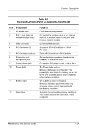
Compaq Evo n150 Hard Drive Connector - Notebook PC
Compaq Evo n150 Hard Drive Connector

Related Manual Pages
Similar Questions

Model Cq2oo3wm
I have recently lost sound to my speakers. I checked the hard drive, plugged in, I checked the volum...
I have recently lost sound to my speakers. I checked the hard drive, plugged in, I checked the volum...
(Posted by bnutter 7 years ago)

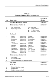
Hp 2510p Hard Drive Connector Part Number
(Posted by kumarmukesh2345 12 years ago)

Compatable Hard Drive
trying to find compatable large capacity hard drive for evo n1000v laptop along with dvdrw and flopp...
trying to find compatable large capacity hard drive for evo n1000v laptop along with dvdrw and flopp...
(Posted by kenstradling 12 years ago)
Hard Drives
looking for hard drive that is larger than 20 or 40 gig that will replace and fit properly in evo n1...
looking for hard drive that is larger than 20 or 40 gig that will replace and fit properly in evo n1...
(Posted by kenstradling 12 years ago)